Vehicle lamp

a technology for vehicle lamps and overhead lights, which is applied in vehicle interior lighting, transportation and packaging, and heating devices, etc., can solve the problems of reducing the visibility of overhead lights installed above the road surface in the forward direction of a vehicle, difficult to miniaturize the headlamps, and difficult to irradiate light of a predetermined luminance or more uniformly over the entire region of overhead lights, so as to achieve the effect of increasing the amount of irradiation light constituting the overhead lights

Inactive Publication Date: 2007-01-25
KOITO MFG CO LTD
View PDF12 Cites 21 Cited by
  • Summary
  • Abstract
  • Description
  • Claims
  • Application Information

AI Technical Summary

Benefits of technology

[0051] Furthermore, the vehicle lamp according to the invention further includes the auxiliary reflecting surface for an overhead sign which is disposed beneath the light source and reflects the light from the light source toward the overhead sign reflecting surface. Thus, an amount of irradiation light constituting the overhead sign distribution light can be increased. This is effective particularly when a light source with a small amount of irradiation light as the light source.

Problems solved by technology

According to such projector-type headlamp, since the upward irradiation light is almost completely removed, there arises a problem that a visibility of overhead signs (OHS) installed above a road surface in the forward direction of a vehicle degrades.
Thus, it is difficult to miniaturize the headlamp.
Therefore, it is difficult to irradiate light of a predetermined luminance or more uniformly over the entire region of the overhead sign.

Method used


Image

  • Vehicle lamp
  • Vehicle lamp
  • Vehicle lamp

Examples


first exemplary embodiment

[0069] First, a first exemplary embodiment of the vehicle headlamp according to the invention will be explained.

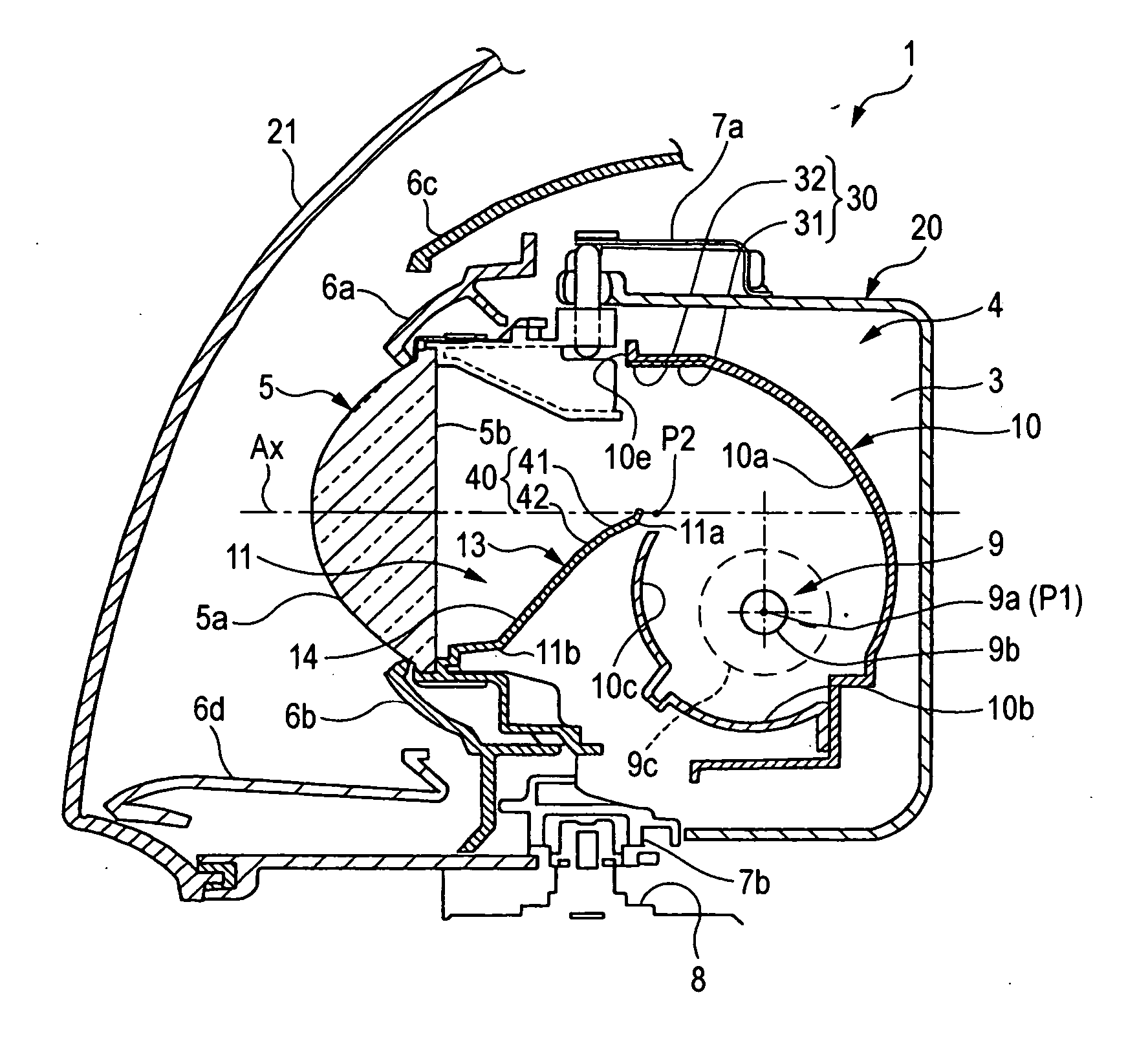
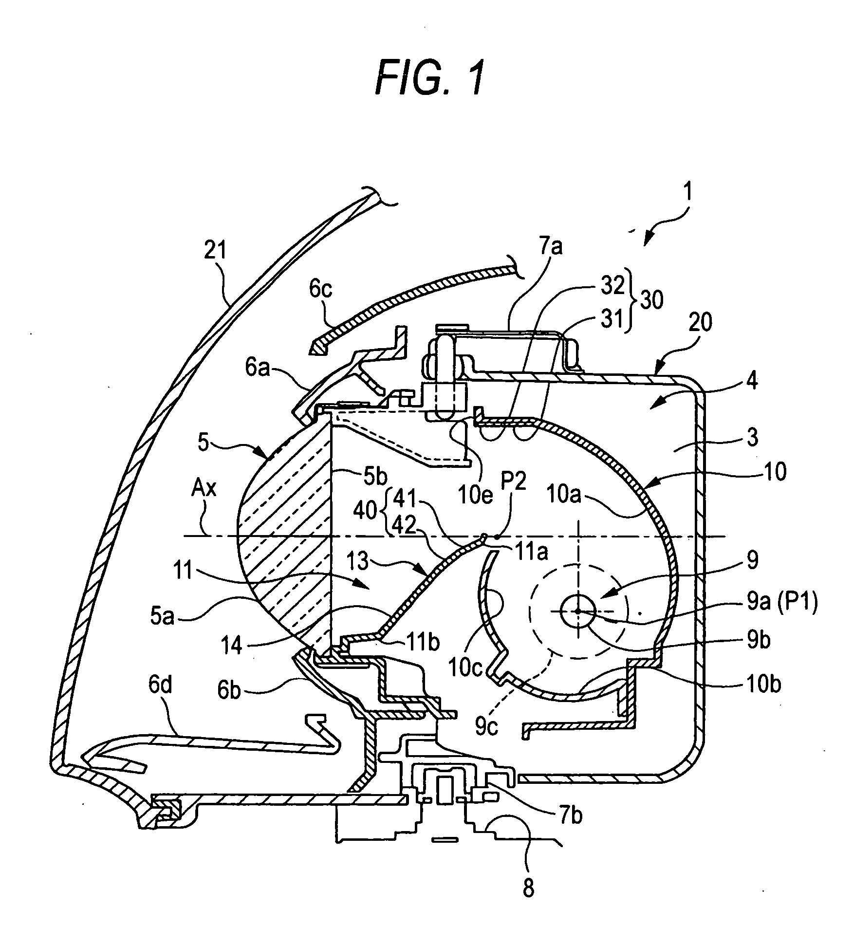
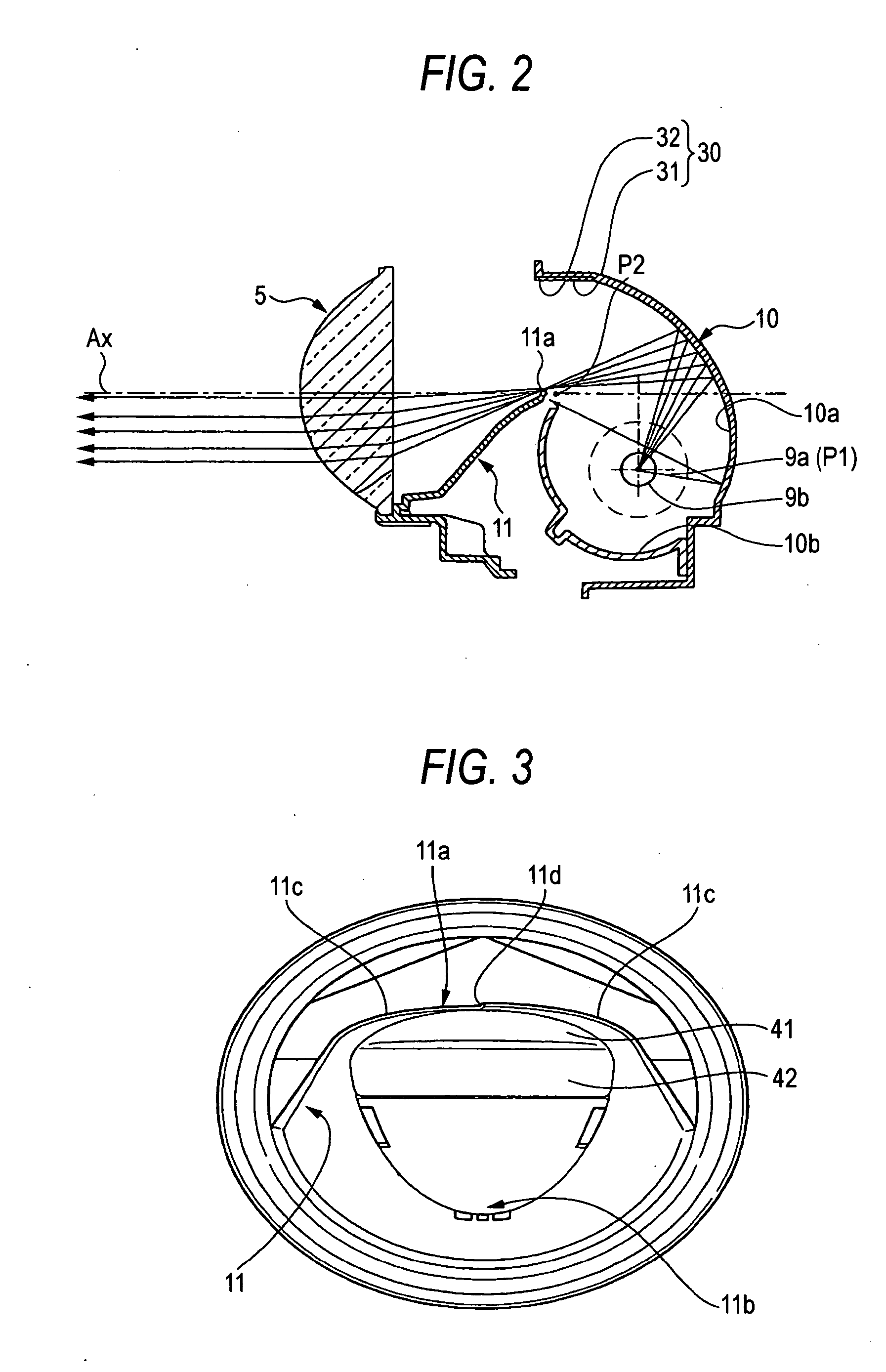
[0070]FIG. 1 is a sectional diagram for explaining the entire configuration of the vehicle headlamp according to the first exemplary embodiment of the invention. FIG. 2 is an optical path diagram showing the basic optical path of the vehicle headlamp according to the exemplary embodiment. FIG. 3 is a diagram of the shade of the vehicle headlamp according to the exemplary embodiment seen from the oblique upper direction of the front side thereof.

[0071] The vehicle headlamp 1 according to the exemplary embodiment includes a projector-type lamp unit 4. The lamp unit 4 is housed within a lamp chamber 3, which is formed by a lamp body 20 and a translucent cover 21 attached to the front side opening portion of the lamp body. A projection lens 5 is provided at the front portion of the lamp unit 4. The outer peripheral side of the projection lens 5 positioned at the front portio...

second exemplary embodiment

[0107] Next, the second exemplary embodiment of the vehicle headlamp according to the invention will be explained.

[0108]FIG. 9 is a sectional diagram for explaining the entire configuration of a vehicle headlamp 100 according to the second exemplary embodiment of the invention. FIG. 10 is an optical path diagram showing the optical path of an overhead sign light. FIG. 11 is a view of the shade of the vehicle headlamp according to the exemplary embodiment seen from the oblique upper direction of the front side hereof. In these figures, portions identical to those of the first exemplary embodiment are referred to by the common symbols, with explanation thereof being omitted in order to avoid the redundant explanation.

[0109] In this exemplary embodiment, the basic configuration is same as that of the first exemplary embodiment. However, the conjurations of the light source bulb 9, the lower reflecting surface 10b and the overhead sign light receiving surface 40 provided near the uppe...


PUM


Abstract

A vehicle lamp is provided with a projection lens; a light source; a shade, which forms a cutoff line; a reflector, which reflects a light from the light source toward the projection lens such that the light passes near an upper end portion of the shade so as to irradiate a forward direction along an optical axis with the light emitted from the projection lens; an overhead sign reflecting surface, which is provided near an upper end edge of the reflector and reflects the light from the light source; and an overhead sign light receiving surface, which is provided near the upper end portion of the shade and reflects the light from the reflecting surface toward the projection lens so as to irradiate upward irradiation light from the projection lens. The overhead sign reflecting surface includes a plurality of reflecting surfaces, which emit reflected light of different patterns.

Description

BACKGROUND OF THE INVENTION [0001] 1. Field of the Invention [0002] The present invention relates to a projector-type vehicle lamp and, in particular, relates to a vehicle lamp in which a distribution light pattern irradiated upward of a cutoff line is generated. [0003] 2. Description of the Related Art [0004] A projector-type headlamp is a lamp for a vehicle in which a light from a light source is reflected by a reflector and the reflected light is projected in the forward direction by a projection lens. If such projector-type headlamp is used for producing a low beam, a shade is provided between the projection lens and the reflector. The shade shields a part of the light reflected from the reflector so as not to irradiate the upward irradiation light from the projection lens. Therefore, a border line of contrast is formed as a cutoff line in the distribution light pattern. [0005] According to such projector-type headlamp, since the upward irradiation light is almost completely rem...

Claims


Application Information

Patent Timeline
Patent Type & Authority Applications(United States)
IPC IPC(8): F21V7/00F21W107/10
CPCF21S48/1388F21V13/10F21S48/145F21S41/172F21S41/255F21S41/32F21S41/321F21S41/323F21S41/336F21S41/338F21S41/365F21S41/43F21S41/60F21S41/675F21S41/689F21W2102/18B60Q1/06B60Q2200/30F21S41/17F21W2107/10
Inventor KINOSHITA, MASAO
Owner KOITO MFG CO LTD
Why Eureka
Try Eureka