
Technique for converting bit rates

a bit rate and bit rate technology, applied in the field of bit rate conversion, can solve the problems of affecting the quality of transmission, affecting the judicious allocation of bandwidth for a number of data streams, and the method requires complex calculations and phase differences compensation,

Inactive Publication Date: 2007-01-25
ECE TELECOM LTD
View PDF5 Cites 9 Cited by
  • Summary
  • Abstract
  • Description
  • Claims
  • Application Information

AI Technical Summary

Benefits of technology

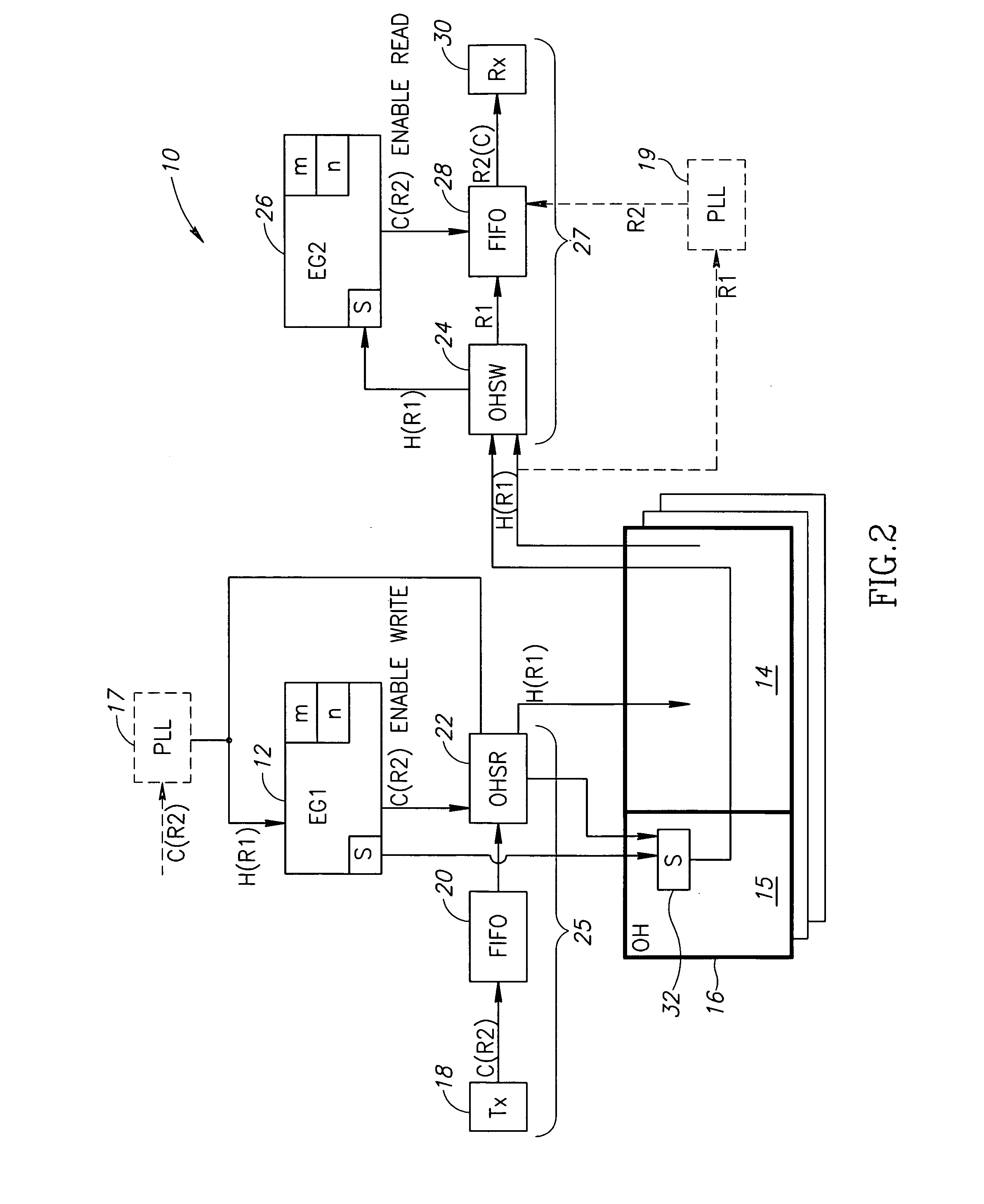
[0012] It is therefore an object of the present invention to provide a simple technique of generation first type / second type (enabling / disabling) signals in a manner ensuring presenting a higher bit rate as a sum of lower bit rates, for example for low jitter transmission of an incoming lower rate data stream over an outgoing higher rate data stream.
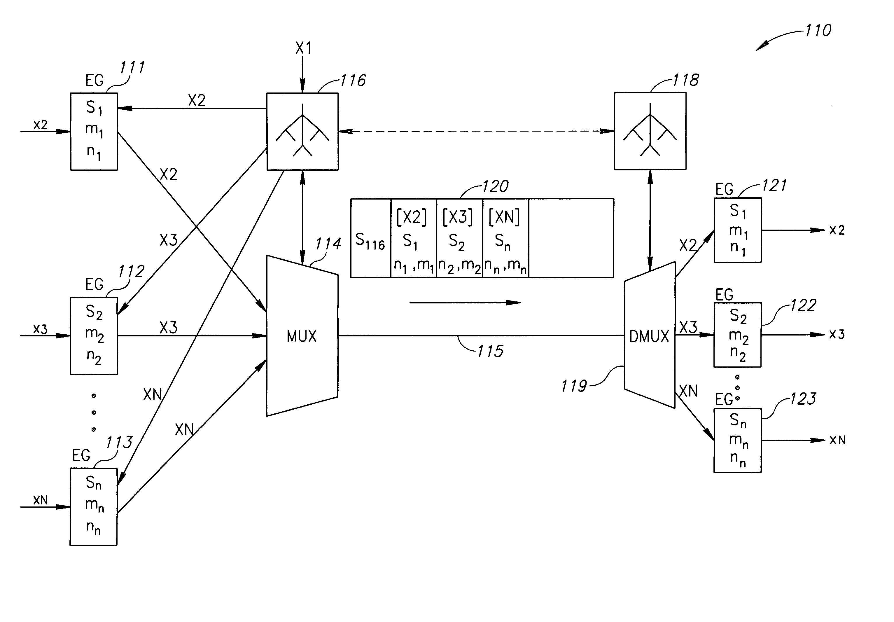
[0071] Owing to that, the same concept may be applied for enveloping and transmitting a number of client's data streams via a high rate transport data stream while preserving the advantage of low jitter.
[0076] Judicial distribution of waste bit rates (waste clocks) may essentially lower the resulting jitter.
[0078] In the most preferred embodiment of the binary tree-like structure, at least one of the Cyclic Generators is the low jitter CG (i.e., capable of uniformly distributing signals of the first type among signals of the second type). Such a binary tree-like structure is more effective to perform bandwidth allocation suitable for low jitter multiplexing.
[0090] The telecommunication system may comprise the binary structure and at least one additional cyclic generator CG (or EG) for mapping at least one of said initial data streams, said at least one additional CG being associated with said binary three-like structure so that one of the component bit rates X2, . . . , XN obtained in the structure is used as the higher bit rate R1 of the additional CG, and a corresponding one of the required bit rates x2, . . . , xN is used as a lower bit rate R2 of the additional CG, the system thereby enabling conversion of at least one lower required bit rate into a higher allocated component bit rate. If the system also comprises a multiplexer, the higher component bit rates can be further multiplexed.

Problems solved by technology

Long and unequal time distances between the “silent” positions in the outgoing data stream degrade the quality of transmission.
The method requires complex calculations and compensation of phase differences introduced by the converter.
In modem communication systems, there is always a problem of judicious bandwidth allocation for a number of data streams.
The above-mentioned technology suffers from complexity both of the method and of the implementation.

Method used


Image

  • Technique for converting bit rates
  • Technique for converting bit rates
  • Technique for converting bit rates

Examples


Embodiment Construction

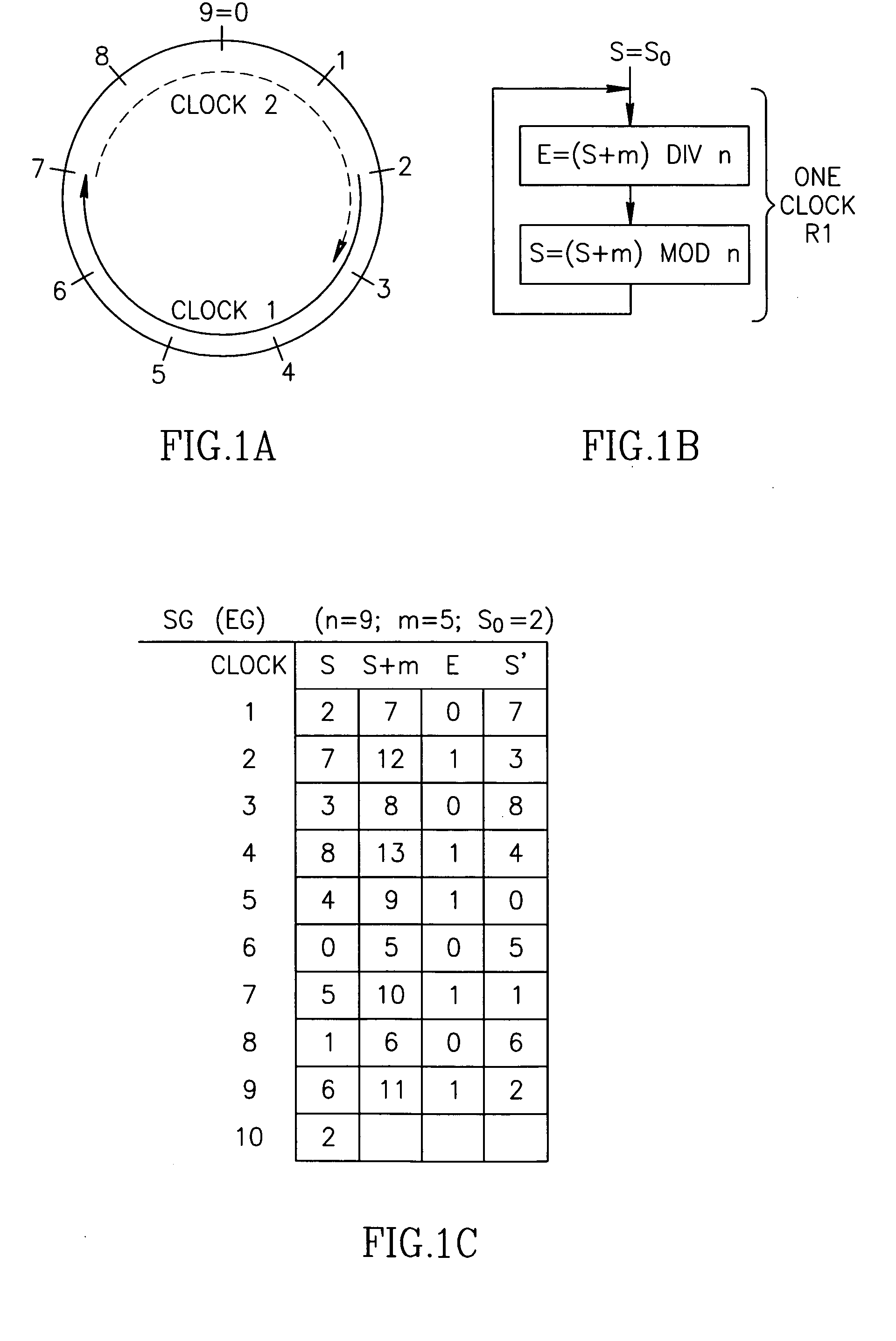
[0103]FIG. 1a schematically illustrates a circular diagram of the proposed cyclic generator CG; let in this particular case it is an enable generator (EG). The function of the EG is to generate enable / disable signals, say for reading data incoming a FIFO with a constant arbitrary client bit rate R2, at another (higher) bit rate R1−for example, to allow further transmission of this data with this another bit rate R1. In the enable generator, R2 =mR1 / n ( R1, for example, is any selected SDH rate), wherein both m and n are integers and m1) there will be m clocks with enabling signals to transform the bit rate R2 into bit rate R1.

[0104]FIG. 1a illustrates the diagram for an exemplary case where n=9, m=5 To begin its operation, the generator EG defines an initial state (condition) S within a cycle being n clocks, at each clock the generator changes the state so that S′=S+m, and acts as follows:

[0105] if S′≧n, a bit from the incoming data is transmitted (ENABLED), and the condition S′r...


PUM


Abstract

A binary tree-like structure for converting bit rates in a telecommunication system, comprising at least one cyclic generator (CG) adapted to present a higher bit rate called R1 substantially as a sum of two lower bit rates called R2 and R3 by cyclically producing, per n clocks of the bit rate R1, m first type signals as clocks of the bit rate R2 and (n−m) second type signals as clocks of the bit rate R3, where m and n are parameters of the CG and integers such, that m<n. The two lower bit rates R2 and R3, based on its parameters m and n, can be presented as follows: R2=mR1 / n, R3=(n−m)R1 / n. The higher bit rate R1 of a particular CG is either obtained from outside of the binary tree-like structure or constitutes a lower bit rate of another, upper range CG of the structure, while each of the lower bit rates R2 or R3 of a particular CG is either dispatched away from the structure or constitutes a higher bit rate of another, lower range CG of the structure.

Description

[0001] The present patent application is a Continuation-In-Part of the U.S. patent application Ser. No. 10 / 445,993 filed on 28 of May 2003 as a national phase of a PCT application claiming priority of Jun. 4, 2002 from IL patent application 150011. Additionally, this CIP application claims priority from IL patent application 169071 filed Jun. 8, 2005.Field of the invention [0002] The present invention relates to a technique for converting bitorates, in particular, to methods and devices for providing bit rates conversion with low jitter and for multiplexing a number of data streams having different bit rates into a common data stream using the proposed ways of conversion. BACKGROUND OF THE INVENTION [0003] Converting a lower bit rate data stream incoming a converter, into a higher bit rate data stream outgoing the converter, is usually provided by inserting between binary words of the incoming lower rate data stream so-called “silent” binary words which fill extra positions not carr...

Claims


Application Information

Patent Timeline
IPC IPC(8): H04J3/02
CPCH04J3/076H03M13/6368
Inventor RUTHSTEIN, JACOBLITINSKY, LEVVIKS, AMIHAL
Owner ECE TELECOM LTD
Learn More