Methods and systems for counterbalancing a scanning beam device

a scanning beam and drive assembly technology, applied in the field of scanning beam devices, can solve the problems of reducing the size of scanning beam systems, affecting image formation and image acquisition of target areas, and lack of low-cost micro-optical systems with a wide field of view (fov)

Active Publication Date: 2007-01-25
UNIV OF WASHINGTON
View PDF55 Cites 27 Cited by
  • Summary
  • Abstract
  • Description
  • Claims
  • Application Information

AI Technical Summary

Benefits of technology

[0008] The present invention provides methods, systems and devices for counterbalancing drive assembly and scanning element of a scanning beam device. The counterbalancing may be carried out with a “virtual mass” and does not require a large mass to counterbalance the drive assembly and scanning element. Consequently, the low-profile size of the housing of the scanning beam device may be maintained.

Problems solved by technology

Scanning beam systems fill the need, but the lack of low cost micro-optical systems with a wide field of view (FOV) have been the most significant barrier for reducing the size of scanning beam systems for use in minimally invasive medical imaging (flexible endoscopes), surveillance, industrial inspection and repair, machine and robotic vision systems, and micro-barcode scanners.
As can be appreciated, actuation of the drive assembly will often cause transverse forces (e.g., accelerations) and torques to the scanning fiber device which may detrimentally affect image formation and image acquisition of the target area.
While such a solution may be useful for larger scanning fiber devices, because the dimensions of small scanning fiber devices (e.g., flexible endoscope) are so small, it may not be possible to place a mass of an appropriate size within the housing of the scanning fiber device to minimize the drive assembly's proximal end attachment movements.

Method used


Image

  • Methods and systems for counterbalancing a scanning beam device
  • Methods and systems for counterbalancing a scanning beam device
  • Methods and systems for counterbalancing a scanning beam device

Examples


Embodiment Construction

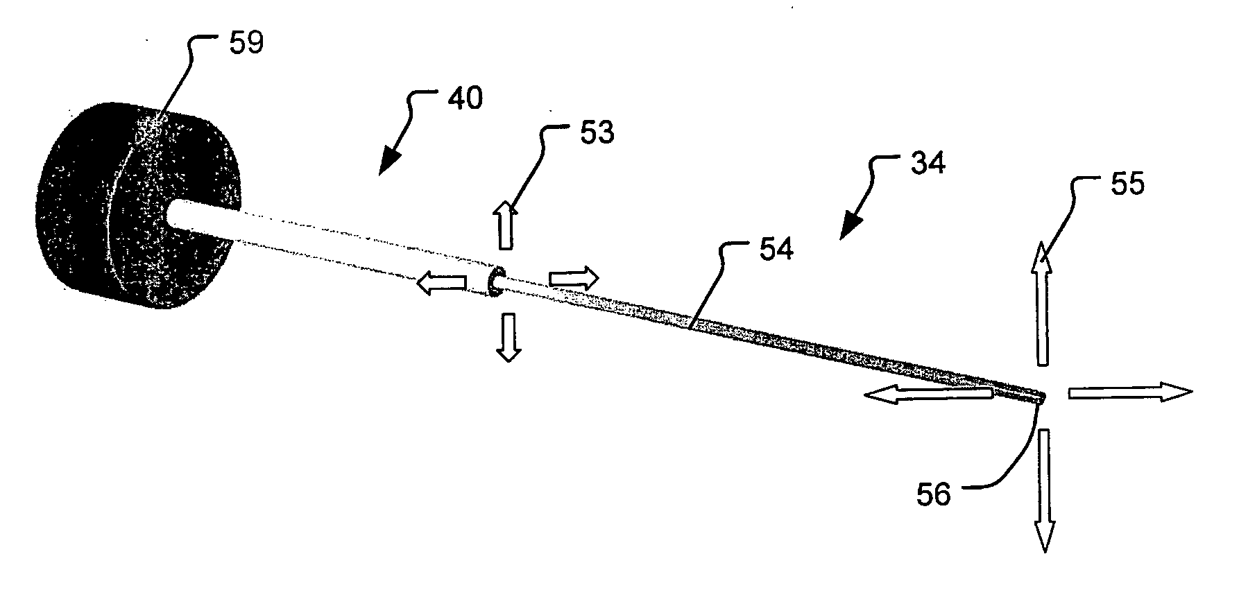
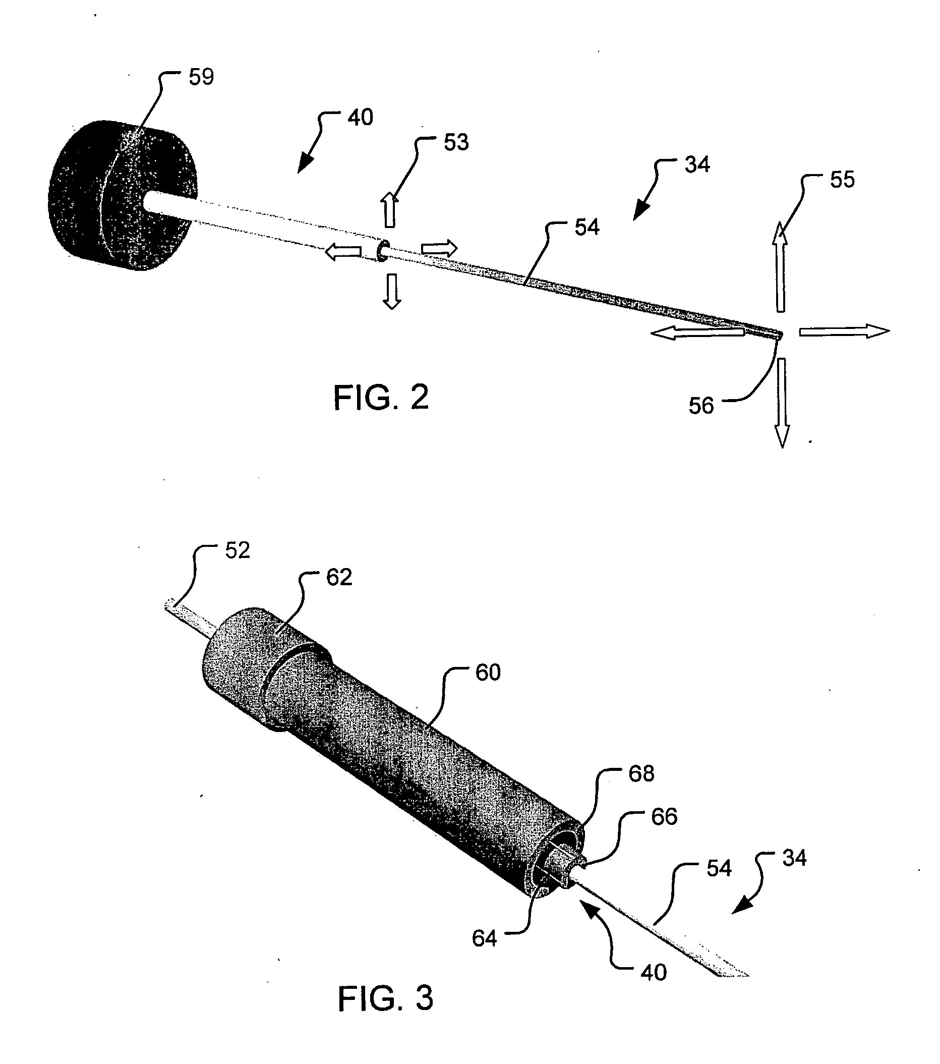
[0024] The present invention provides methods and scanning beam devices that comprise a counterbalance to counterbalance forces and / or torques caused by the drive assembly and by the actuation of the scan element.

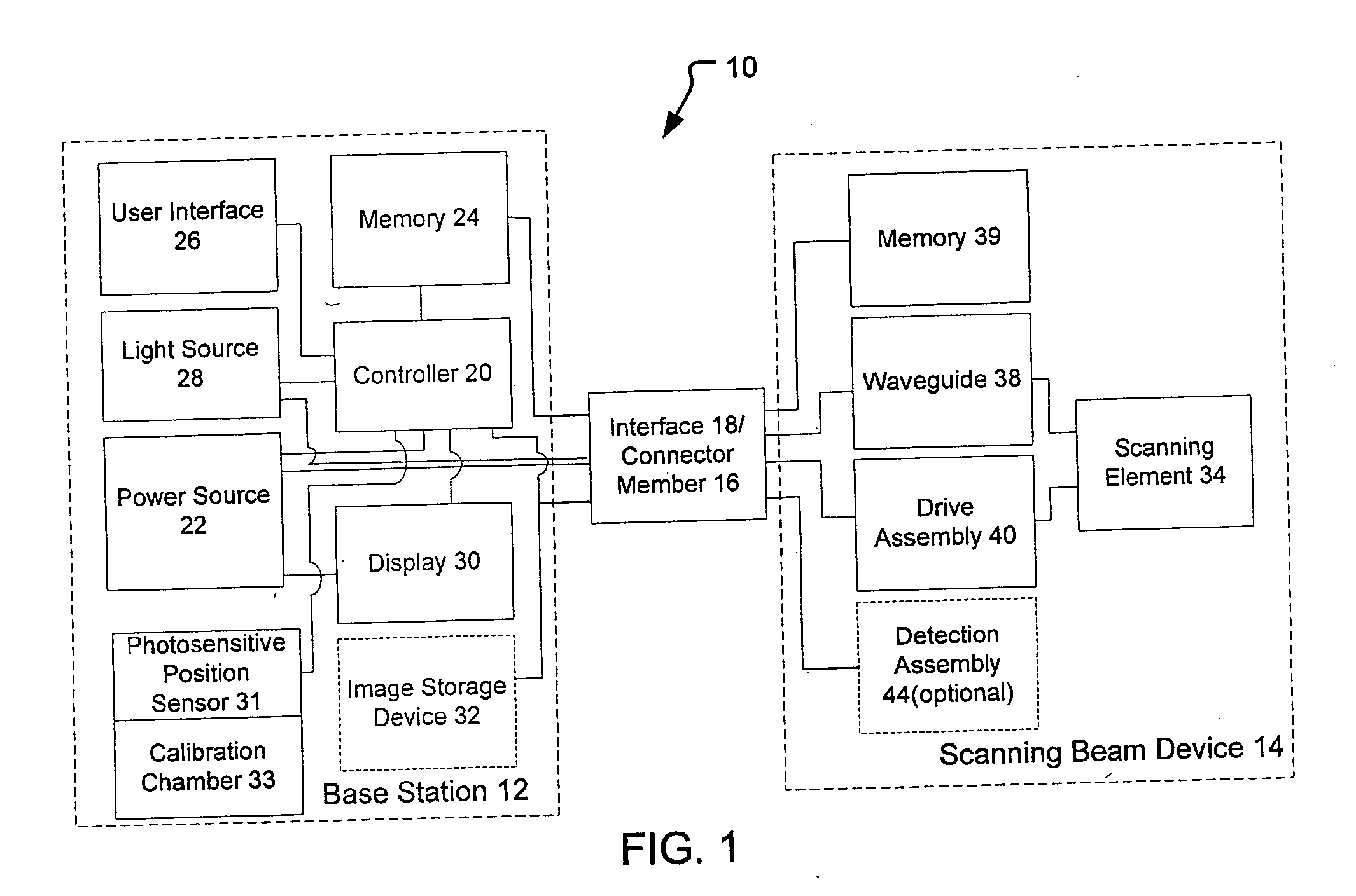
[0025] Scanning beam systems of the present invention generally include a scanning beam device and a base station for controlling the scanning beam device. The scanning beam devices of the present invention may take on a variety of forms, but are typically in the form of a flexible or rigid endoscope, catheter, fiberscope, microscope, or a boroscope. The scanning beam devices of the present invention may be a limited use device (e.g., disposable device) or a multiple-use device. If the device is for medical use, the scanning beam devices of the present invention will generally be sterile, either being sterilizable or being provided in hermetically sealed package for use.

[0026] The scanning beam devices of the present invention include a scanning element for scanning a bea...


PUM


Abstract

Methods and system for counterbalancing accelerations and/or torques caused by actuation of an actuation element and a scanning element. A scanning beam device may comprise a counterbalance to generate forces and/or torques that are substantially equal and substantially opposite to the forces and/or torque generated by the scanning of the actuation element.

Description

BACKGROUND OF THE INVENTION [0001] The present invention is directed to scanning beam devices. More specifically, the present invention is related to methods and systems for counterbalancing a drive assembly in a scanning fiber device. [0002] There is a growing market for micro-optical displays and small image acquisition systems (e.g., cameras). Scanning beam systems fill the need, but the lack of low cost micro-optical systems with a wide field of view (FOV) have been the most significant barrier for reducing the size of scanning beam systems for use in minimally invasive medical imaging (flexible endoscopes), surveillance, industrial inspection and repair, machine and robotic vision systems, and micro-barcode scanners. [0003] To that end, an improved scanning beam system has recently been developed by the University of Washington which involves the use of a cantilevered optical fiber that is scanned in one or two dimensions to project light out of the end of the optical fiber to ...

Claims


Application Information

Patent Timeline
Patent Type & Authority Applications(United States)
IPC IPC(8): G02B6/26
CPCG02B6/262G02B6/3578G02B6/3502
Inventor MELVILLE, CHARLES
Owner UNIV OF WASHINGTON
Why Eureka
Try Eureka