Non-homogenous multi-layer core holder for CT (computed tomography) scanning

A core holder, CT scanning technology, applied in instruments, scientific instruments, suspension and porous material analysis, etc., can solve problems such as impermeability, achieve excellent dielectric properties, good self-lubrication, and reduce experimental effect of error

Active Publication Date: 2011-08-24
PETROCHINA CO LTD
View PDF4 Cites 26 Cited by
  • Summary
  • Abstract
  • Description
  • Claims
  • Application Information

AI Technical Summary

Problems solved by technology

In addition, the metal casing used by conventional core holders has a strong absorption of X-rays, making X-rays "impenetrable" to the metal casing, and the "artifacts" caused by radiation hardening, which affect the application of CT technology Main Factors in Homogeneity Studies

Method used


Image

  • Non-homogenous multi-layer core holder for CT (computed tomography) scanning
  • Non-homogenous multi-layer core holder for CT (computed tomography) scanning
  • Non-homogenous multi-layer core holder for CT (computed tomography) scanning

Examples


Embodiment 1

[0019] Example 1 Heterogeneous Multilayer Core Holder for CT Scanning

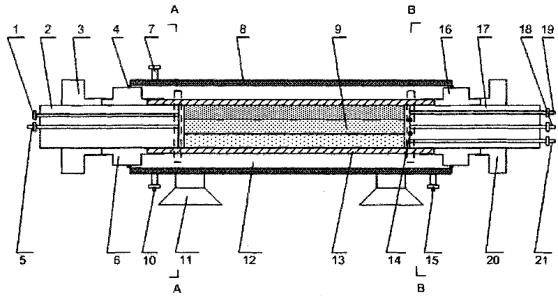
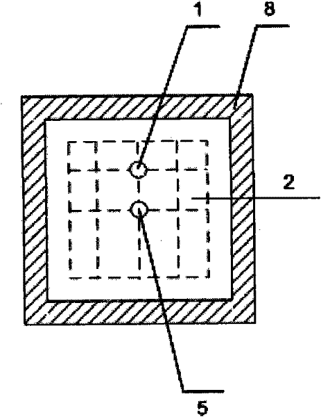
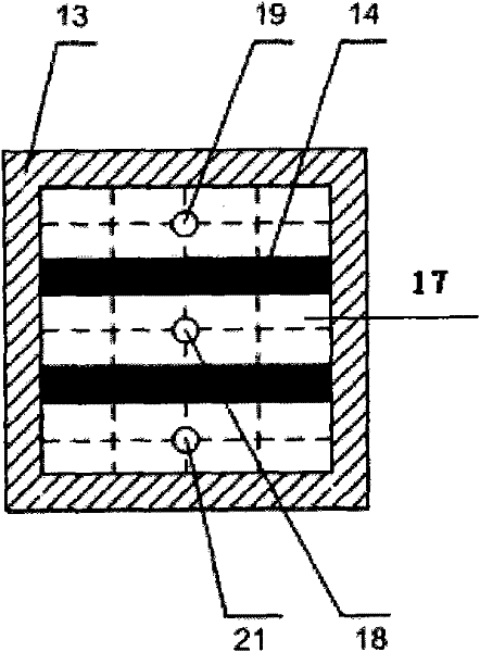
[0020] Figure 1-3 Shown is a schematic structural diagram of a heterogeneous multilayer core holder for CT scanning in a preferred embodiment of the present invention, a heterogeneous multilayer core holder for CT scanning consists of a housing 8, rubber Tube 13, rock core left plug 2, rock core right plug 17, left fixed sleeve 6, right fixed sleeve 16, left fastening sleeve 3, right fastening sleeve 20 and fixed bracket 11 constitute;

[0021] The polyether ether ketone resin casing 8 is cylindrical, and the rubber casing 13 is placed inside the casing 8, coaxial with the casing 8; the multi-layer core model 9 is located in the inner cavity of the rubber casing 13; the left plug of the rock core 2, the right plug of the rock core 17 is detachably abutted against the two ends of the multi-layer core model 9 in the rubber tube 13, and its shape and size are consistent with the inner wall of the rubber tub...

Embodiment 2

[0022] Example 2 CT scan evaluation experiment of water flooding efficiency of heterogeneous model in layer

[0023] Firstly, three natural oil reservoir cores collected from different depths were taken to make cuboid single-layer core models with the same specifications. Measure the porosity and air permeability of each single-layer core model respectively; saturate each single-layer core with formation water, and measure the water-phase permeability respectively; then carry out oil flooding on each single-layer core respectively, and measure the oil permeability after reaching the state of bound water; The effective permeability of the facies and calculate the irreducible water saturation of each monolayer core.

[0024] The rock cores of each layer containing irreducible water are placed in the rock core chamber of the rock core holder described in embodiment 1 according to the anti-rhythm arrangement; the rock core upper and lower plugs and upper and lower fixing sleeves o...


PUM


Abstract

The invention relates to a non-homogenous core holder for CT (computed tomography) scanning. A rubber cylinder is arranged in a shell; a core left top and a core right top arranged in the rubber cylinder and push against two ends of a multi-layer core mold; a core containing chamber which accommodates the multi-layer core mold is defined by the inner wall of the rubber cylinder, the core left top and the core right top; a left fixed sleeve and a right fixed sleeve are respectively sleeved on the core left top and the core right top; an enclosed annular confining pressure space is defined by the outer wall of the rubber cylinder, the left fixed sleeve, the right fixed sleeve and the inner wall of the shell; the shell is provided with a confining pressure interface, a confining pressure exhaust hole and a confining pressure discharging hole; the core left top is internally provided with a liquid inlet and a core exhaust hole; and the core right top is internally provided with a middle-layer liquid outlet, an upper-layer liquid outlet and a lower-layer liquid outlet. The holder can detect the on-way distribution of fluid saturation in each layer section in a non-homogenous layer on line in real time, and also can observe fluid channeling among layers.

Description

technical field [0001] The invention relates to a test device for simultaneous injection and delamination mining in simulated oilfields, in particular to a heterogeneous multi-layer rock core holder for CT scanning. Background technique [0002] CT technology has developed rapidly and has been widely used in core analysis, core heterogeneity measurement, core sample selection, fracture quantitative analysis, online saturation measurement, flow experiment research, etc. as a conventional testing technology in core analysis. Visually characterize the pore structure, heterogeneity, and remaining oil distribution of the rock through quantitative and image analysis of the physical properties of the rock; conduct visual research on the displacement process to deeply understand the oil recovery mechanism, monitor fluid dispersion and channeling characteristics, and understand aggregation The impact of material flooding on increasing the swept area and revealing the mechanism of for...

Claims


Application Information

Patent Timeline
Patent Type & Authority Applications(China)
IPC IPC(8): G01N15/08G01N23/083
Inventor 吕伟峰张祖波严守国罗蔓莉刘庆杰
Owner PETROCHINA CO LTD
Why Eureka
Try Eureka