
Production of backing component for carpet products

a technology of backing components and carpet products, which is applied in the direction of synthetic resin layered products, floor coverings, textiles and paper, etc., can solve the problems of high viscosity, excessive conveyor belt wear and other problems, and difficult doctoring or calendar rolling of material to a precise gauge, etc., to achieve the effect of high filler content and high filler conten

Inactive Publication Date: 2007-01-25
INTERFACE INC
View PDF11 Cites 5 Cited by
  • Summary
  • Abstract
  • Description
  • Claims
  • Application Information

AI Technical Summary

Benefits of technology

This invention provides a new type of plastic composition for a carpet backing that solves previous problems. The composition contains PVC resin, plasticizer, and filler. The composition has a preferred viscosity and thickness. The composition can be applied as a floor covering and has good stability. The invention also provides methods for making the floor covering by feeding the plastic composition through a slot-die and adding additional layers. The new composition can be used for various floor covering products.

Problems solved by technology

However, a doctor bar is not suitable for such high viscosity compositions because it is very difficult precisely to meter such compositions to the desired thickness, and use of a calendar roll with such high viscosity compositions can result in excessive conveyor belt wear and other problems.
Thus, simply pouring onto a carpet web or a conveyor belt the composition having filler (and thus a high viscosity) and doctoring or calendar rolling the material to a precise gauge is extremely difficult.
Extruders, however, are not ideal for extruding materials having a high filler content.
Extruders represent a large capital investment and are extremely costly to maintain and repair.
These grit-like fillers thus wear excessively on the extruder parts and thus require their frequent replacement, which is extremely costly.
Thus, use of extruders with compositions having high filler content is undesirable.

Method used


Image

  • Production of backing component for carpet products
  • Production of backing component for carpet products
  • Production of backing component for carpet products

Examples


example 1

[0021] In one embodiment of this invention the following materials were mixed utilizing a Nauta mixer (although other mixers, such as a horizontal plow mixer, may be used) to form a plastisol:

ComponentAmount by weightGeon-138 (PVC resin)15%di-isononyl phthalate (plasticizer)15%Fly ash (filler)70%

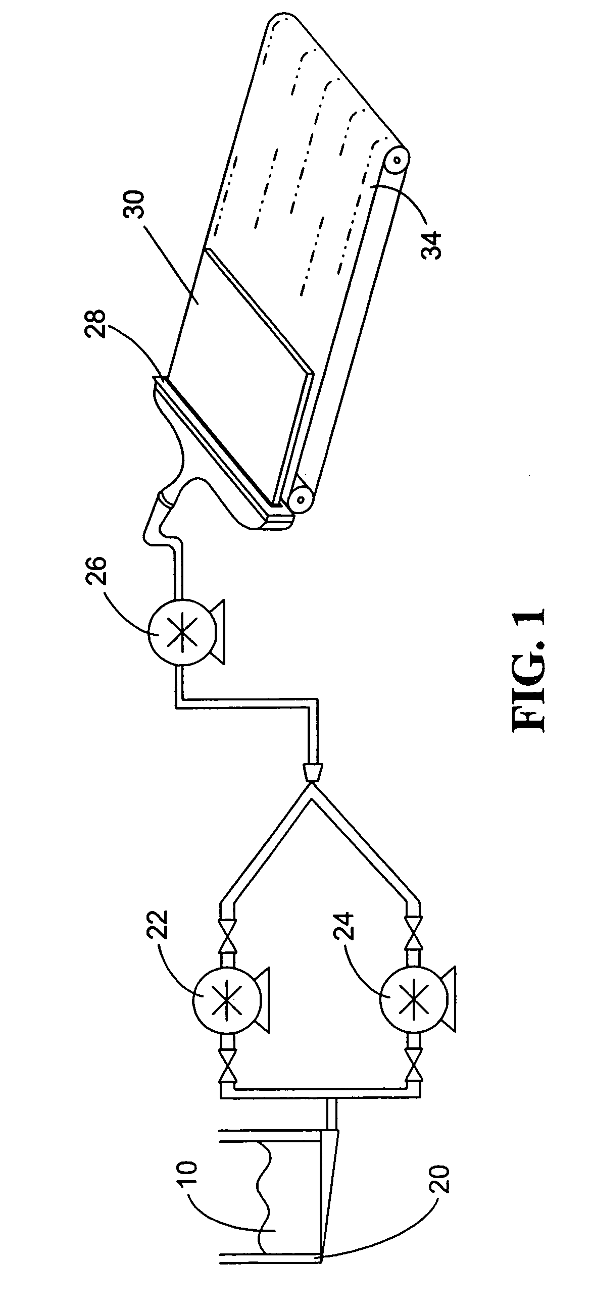
[0022] As is illustrated in the schematic diagram of FIG. 1, the plastisol 10 was transferred to a plastisol holding tank 20 illustrated in FIG. 1. Two diaphragm pumps 22 and 24, such as those manufactured by Wilton and preferably having three-inch inlet and outlet ports, were used to transfer the plastisol to a gear pump 26. Gear pump 26, such as the Maag gear pump (model number RX 110 / 110), had a flow rate of between 70 pounds / minute and 90 pounds / minute and preferably approximately 83 pounds / minute.

example 2

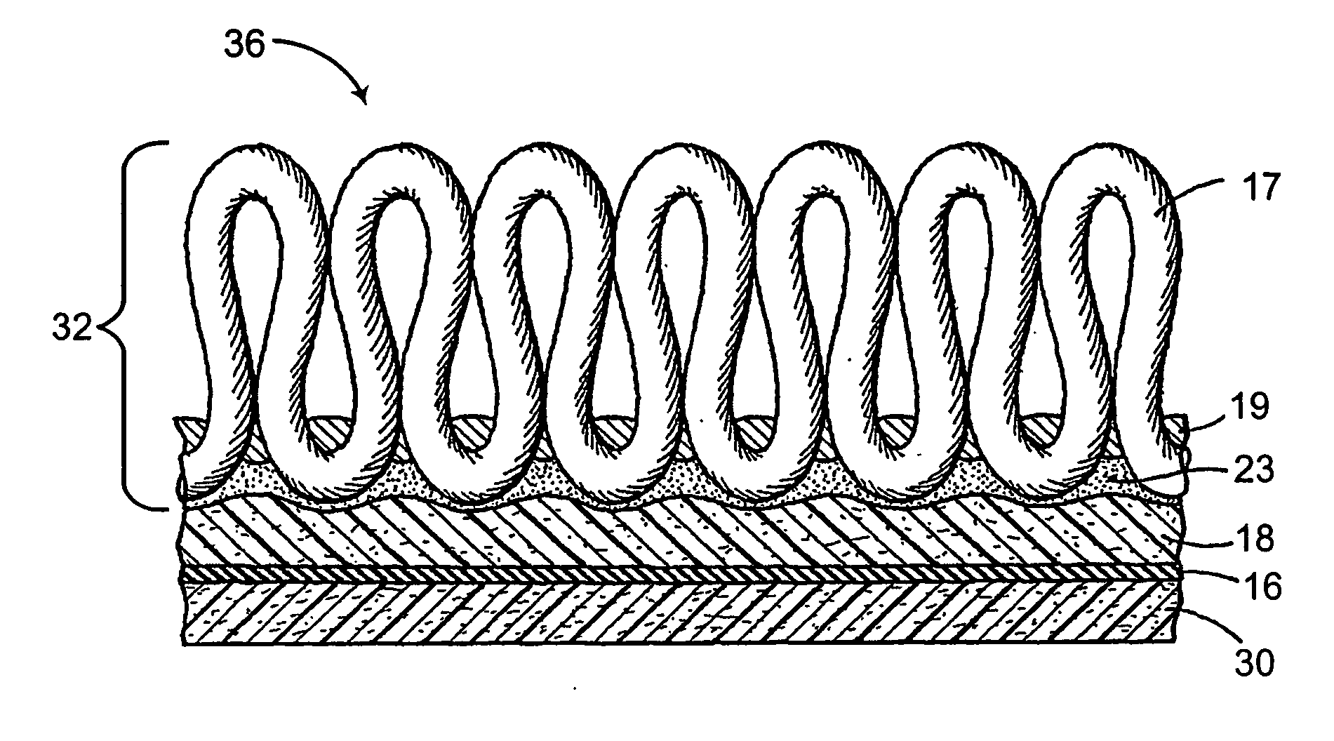
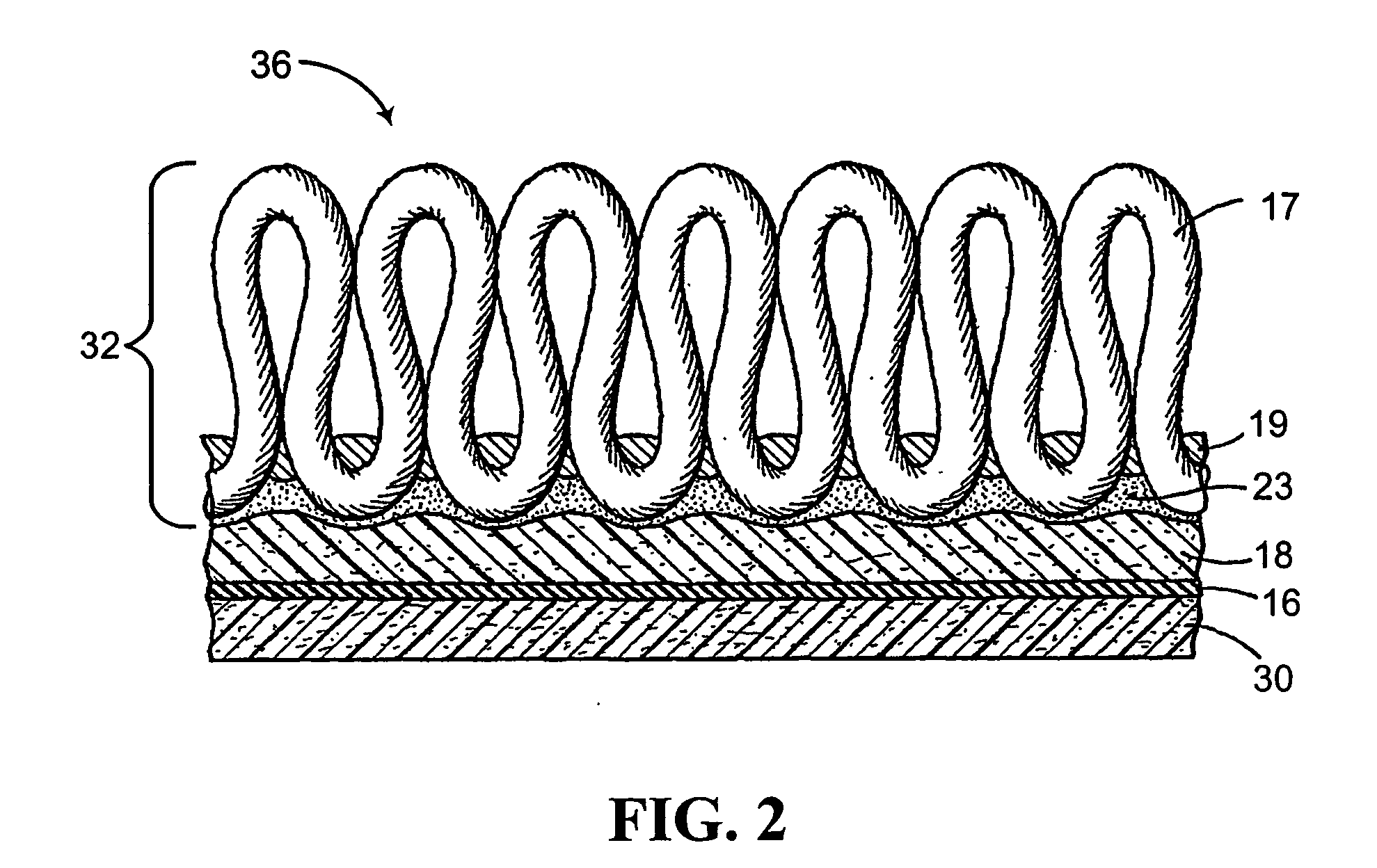
[0023] In one embodiment (see FIGS. 1 and 2), gear pump 26 feeds a slot die 28 positioned so that a sheet 30 of plastisol 10 dispensed from the slot die 28 rests on an advancing conveyor 34. Sheet 30 is desirably 20 to 75 mils thick, more desirably 20 to 50 mils, and most desirably approximately 25 mils thick (0.025 inches). After deposit of the sheet 30 on the conveyor 34 (in FIGS. 1 and 2), additional backing structures may be, but do not have to be, introduced on top of the sheet 30. For example, in a preferred embodiment, a stabilizing layer 16 (such as a fiberglass scrim) is positioned on top of the sheet 30, after which another layer of PVC 18 (which may be introduced via another slot die or by a traditional metering process) is applied atop the fiberglass scrim 16. A carpet web 32 is then positioned on top of the upper layer of PVC 18, which serves to bond the carpet web 32 to the underlying backing composite. FIG. 2 illustrates the cross-section of this finished carpet compo...

example 3

[0024] In another embodiment (see FIGS. 3 and 4), gear pump 26 feeds slot die 28 positioned so that the sheet 30 of plastisol 10 dispensed from the slot die 28 rests on an advancing upside down carpet web 32 that itself rests on conveyor 34. Sheet 30 is desirably 20 to 75 mils thick, more desirably 20 to 50 mils and most desirably approximately 25 mils thick (0.025 inches). Deposit of the sheet 30 on the advancing carpet web 32 forms a carpet composite 40 from which individual tiles may be cut utilizing techniques well known in the industry. As with the embodiment of FIG. 2, additional layers of material may be deposited on top of the sheet 30 to form alternative carpet composites than that illustrated in FIG. 4.


PUM

PropertyMeasurementUnit
viscosityaaaaaaaaaa
thicknessaaaaaaaaaa
thicknessaaaaaaaaaa

Abstract

Disclosed are plastic compositions for a carpet backing having from about 5 to about 25% by weight PVC resin, from about 5 to about 25% by weight plasticizer, and from about 50 to about 90% by weight filler. In a preferred embodiment, the plastic composition is about 15% by weight Geon-138, about 15% by weight di-isononyl phthalate, and about 70% by weight fly ash. Also disclosed are methods for forming backings for floorcoverings using the disclosed plastic compositions. In preferred embodiments, a plastic composition is applied through a slot-die directly to the underside of a carpet or alternatively onto a conveyor belt on top of which the carpet or floorcovering may be subsequently positioned.

Description

CROSS REFERENCE TO RELATED APPLICATION [0001] This application claims benefit of U.S. Provisional Patent Application Ser. No. 60 / 690,256, filed Jun. 14, 2005, the contents of which are incorporated herein by reference.FIELD OF THE INVENTION [0002] This invention relates to compositions, apparatuses, and methods for forming a backing component for carpet products, including carpet tiles. BACKGROUND OF THE INVENTION [0003] Carpet products, including carpet tiles, typically have a fiber-containing pile face attached to a primary backing and, attached to the underside of the primary backing, a multi-component secondary backing containing a variety of materials that impart desired physical properties, including weight, stability, stiffness, durability, under-foot comfort, and resistance to cupping and curling, among other properties. [0004] One of the materials conventionally used in carpet tile secondary backing is polyvinyl chloride (“PVC”). See, for example, U.S. Pat. Nos. 4,010,301, ...

Claims


Application Information

Patent Timeline
Patent Type & Authority Applications(United States)
IPC IPC(8): B32B33/00B32B3/02D05C15/00
CPCB32B5/22D06N7/0076B32B37/15B32B2327/06B32B2471/02C08K3/22C08K3/26C08K5/12C08K2003/265B32B27/30D06N2203/048D06N2205/026D06N7/0081C08L27/06Y10T428/23993Y10T428/23979B32B27/20B32B37/153B32B7/12B32B27/304B32B27/12
Inventor LEES, DONALD WALKER
Owner INTERFACE INC
Learn More