Controlling a voltage-to-frequency ratio for a variable speed drive in refrigerant systems

a variable speed drive and voltage-to-frequency ratio technology, which is applied in the field of refrigerant systems, can solve the problems of unrealistic transformers, impractical voltage adjustments in prior systems, and desirably increasing frequency of operation, so as to maximize the strength of the motor, improve the efficiency of the compressor, and improve the effect of the compressor efficiency

Inactive Publication Date: 2007-02-01
CARRIER CORP
View PDF24 Cites 35 Cited by
  • Summary
  • Abstract
  • Description
  • Claims
  • Application Information

AI Technical Summary

Benefits of technology

[0007] The inventors have determined that a ratio of voltage-to-frequency for the motors of the components in a refrigerant system such as a compressor, fan or pump should vary with operating and environmental conditions. As an example, to improve the compressor efficiency and at the same time maximize its motor strength, it would be desirable to operate the compressor at an optimum voltage. The optimum voltage is dependent upon motor load.

Problems solved by technology

Similarly, the frequency of operation will desirably increase with increased loads.
Voltage adjustments are impractical in the prior systems that rely upon constant frequency and voltage main line supplies.
Furthermore, transformers are unrealistic as they are bul

Method used


Image

  • Controlling a voltage-to-frequency ratio for a variable speed drive in refrigerant systems
  • Controlling a voltage-to-frequency ratio for a variable speed drive in refrigerant systems

Examples


Embodiment Construction

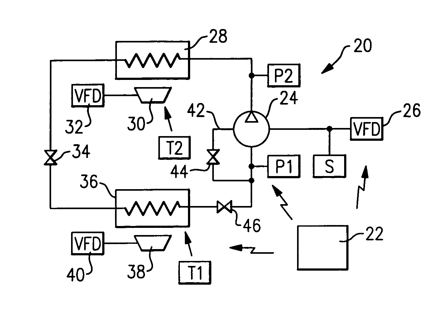
[0020] A basic refrigerant system 20 is illustrated in FIG. 1. An electronic control 22 controls several features within the refrigerant system 20. In particular, a compressor 24 is powered by a motor having a variable speed drive (or variable frequency drive) 26 in communication with the control 22. The compressor compresses refrigerant and delivers it downstream to a condenser 28. A fan 30 moves air over the condenser 28 and is provided with a variable speed drive 32. Downstream of the condenser 28 is an expansion device 34, and downstream of the expansion device 34 is an evaporator 36. A fan 38 moves air over the evaporator 36 and is controlled by a variable speed drive 40. An optional suction modulation valve 46 modulates the flow of refrigerant entering the compressor 24. An optional unloader line 42 with an optional unloader valve 44 selectively allows partially or completely compressed refrigerant to be returned from the compressor 24 back to a suction line for the compressor...


PUM


Abstract

A refrigerant system is provided with at least one variable frequency drive. In the past, the variable frequency drives were operable such that the voltage-to-frequency ratio remained constant regardless of operation. The present invention realizes that variations in the voltage-to-frequency ratio may be desirable, and the refrigerant system control drives the motors associated with relevant refrigerant system components to reach an optimum voltage-to-frequency ratios in order to achieve higher efficiency, provide operational safety and prevent nuisance shutdowns.

Description

BACKGROUND OF THE INVENTION [0001] This application relates to a refrigerant system wherein a motor for at least one component in a refrigerant system is provided with a variable frequency control, and a ratio of the frequency to voltage provided by this control is adjusted to be at an optimum level. [0002] Refrigerant systems are utilized in many air conditioning and heat pump applications for cooling and / or heating the air entering an environment. The cooling or heating load on the environment may vary with ambient conditions, and as the temperature and / or humidity levels demanded by an occupant of the environment change. [0003] In some refrigerant systems, a single compressor is utilized to compress the refrigerant and move the refrigerant through the cycle connecting indoor and outdoor heat exchangers in a closed loop. However, under many circumstances, it would be desirable to have the ability to vary the capacity, or amount of cooling or heating provided by the refrigerant sys...

Claims


Application Information

Patent Timeline
IPC IPC(8): F25D17/00F25B49/00
CPCF25B41/043F25B49/025F25B2600/021Y02B30/743F25B2600/111F25B2600/112Y02B30/741F25B2600/0261Y02B30/70F25B41/22
Inventor LIFSON, ALEXANDERTARAS, MICHAEL F.
Owner CARRIER CORP
Why Eureka
Try Eureka