Solid-liquid separating method,solid-liquid separator and solidified product

a solid-liquid separation and separation method technology, applied in separation processes, filtration separation, moving filter elements, etc., can solve the problems of insufficient recycling of sludge concentrated as a result of solid-liquid separation, inability to recycle sludge, and inability of known sludge solidification apparatus to work with such sludge. to achieve the effect of convenient recycling

Active Publication Date: 2007-02-01
NTN CORP
View PDF6 Cites 35 Cited by
  • Summary
  • Abstract
  • Description
  • Claims
  • Application Information

AI Technical Summary

Benefits of technology

[0047] In the compressed solidified product referred to above, each of the filters may be in the form of a sheet. The sheet-like filters are easy to handle. Also, each of the filters is preferably a paper filter made of plant fibers. In the case where the filters are made of plant fibers, those filters will be burned out, when the compressed solidified product is charged into the steel making furnace and, therefore, the presence of the filters in the compressed solidified product does not affect the quality of a steel material eventually produced and, also, exhaust gases emitted from the filters when the latter are burned will not constitute a cause of environmental pollution.

Problems solved by technology

The solid-liquid separating method utilizing the filter or the low pressure filter press has been recognized to generate a processed sludge still having high content of liquid, resulting in such problems that not only can a sufficient amount of the processing liquid be recovered, but the sludge concentrated as a result of the solid-liquid separation cannot be recycled and is generally disposed of in land reclamation.
However, such known sludge solidifying apparatus cannot work sufficiently with such sludge as sludge produced during honing, sludge produced during super-processing, sludge produced during lapping, and sludge produced during grinding of rolling elements such as, for example, bearing rollers and steel balls, because of the following reason.
For this reason, the conventional sludge solidifying apparatus referred to above cannot be satisfactorily used for solidifying or briquetting those sludge.
Not only does the flow of the ground wastes outwardly of the mold unit 51 through the mechanical gaps δ1 and δ2 discussed above render solidification or briquetting to be difficult to achieve, but the eventually recovered liquid component is still mixed with some of the ground wastes and, therefore, the processing liquid recovered cannot be reused satisfactorily, requiring the recovered processing liquid to be filtered even after the recovery thereof.
However, it has been found that once the metallic filter is clogged, filtering no longer occurs and the metallic filter must be regularly replaced with a fresh one, requiring a complicated and time-consuming maintenance work.
However, both of those methods are incapable of reducing the liquid content of the sludge sufficiently.
For these reasons, the efficiency of recovery of the processing liquid is so insufficient as to result in incapability of recycling the remaining concentrated sludge.

Method used


Image

  • Solid-liquid separating method,solid-liquid separator and solidified product
  • Solid-liquid separating method,solid-liquid separator and solidified product
  • Solid-liquid separating method,solid-liquid separator and solidified product

Examples


first embodiment

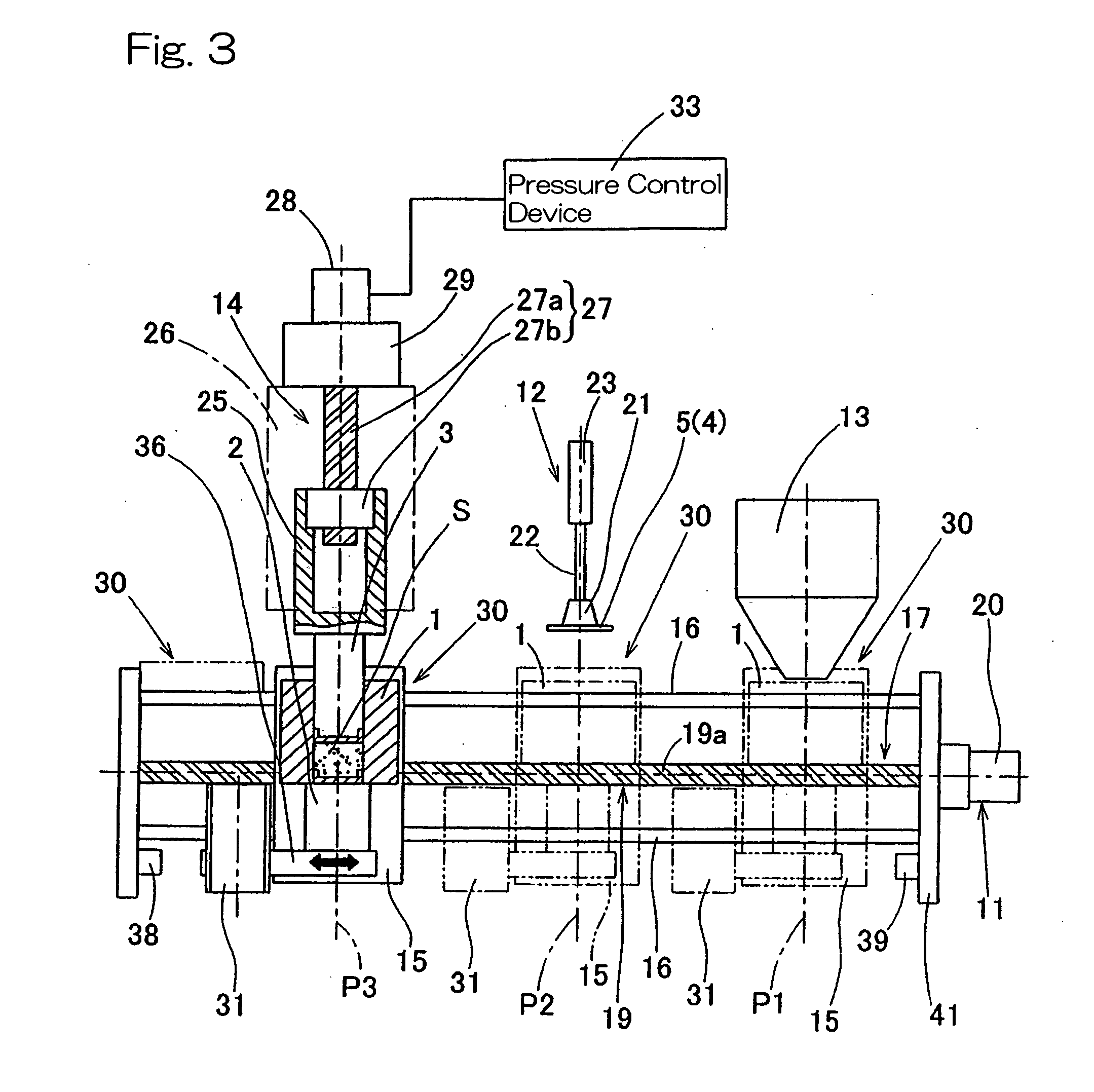
[0121]FIG. 10 is a fragmentary longitudinal sectional view of a portion of the solid-liquid separating apparatus according to another preferred embodiment of the present invention, showing the relation between a nozzle head, which forms means for injecting a liquid bonding agent, and the mold unit 1. The solid-liquid separating apparatus according to the embodiment shown in FIG. 10 is substantially similar to that described hereinbefore in connection with the first embodiment, but is additionally provided with means for and a process step of injecting a bonding agent or a hardening agent.

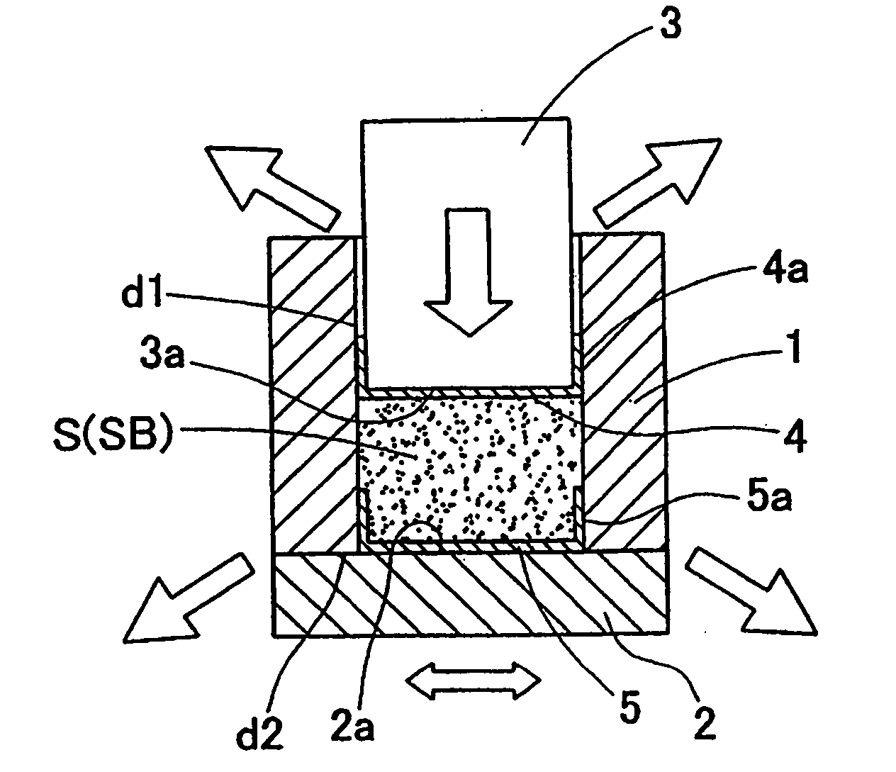
[0122] As is well known to those skilled in the art, it often occurs that depending on the material constituting the slurry S, the slurry S would not be solidified merely by means of the compressing process. If such a slurry S is desired to be solidified, injection of the bonding agent A or the hardening agent into the compressed solid body within the mold unit 1, which has already been compressed i...

second embodiment

[0125] According to the present invention described above, after the slurry S has been compressed within the mold unit 1 by means of the press machine 14 in the manner described hereinbefore, the pressing rod 3 is retracted out of the mold unit 1 and the injection nozzle head 45, shown in FIG. 10, is inserted into the mold unit 1 at the additional indexed position for injection to thereby inject the bonding agent A or the hardening agent.

[0126] Where the bonding agent A or the hardening agent is injected into the mold unit 1 after the slurry S within the mold unit 1 has been compressed, unlike the case in which the bonding agent or the hardening agent is injected at a stage before the slurry is compressed, the liquid components squeezed out from the slurry S as a result of the compression does not mix in the bonding agent or the hardening agent and, therefore, the liquid components as squeezed out from the slurry can be recovered. Also, since after the slurry S within the mold unit ...


PUM

PropertyMeasurementUnit
particle sizeaaaaaaaaaa
diameteraaaaaaaaaa
pressureaaaaaaaaaa

Abstract

To provide a reliable solid-liquid separating method and apparatus for a slurry, even though the solid component of the slurry is finely divided particles and/or of a shape difficult to entangle, without exudation through gaps in processed portions and, also, with no need to exercise a maintenance work such as replacement of filters, a solid-liquid separating apparatus includes a mold having a cylindrical inner peripheral surface, a gate for opening and closing a second open end of the mold, and a pressing rod slidable into the mold to compress the slurry. Sheet-like fibrous filters are placed on a leading end face of the pressing rod and an inner surface of the gate to seal gaps between the mold and the pressing rod and between the gate and mold. With the filters so placed, the slurry within the mold unit is compressed to provide a solidified product, thereby accomplishing solid-liquid separation.

Description

BACKGROUND OF THE INVENTION [0001] 1. Field of the Invention [0002] The present invention relates to a solid-liquid separating method for separating a slurry of a kind containing a mixture, of a liquid processing agent and solid particulate wastes, produced during a machining of metals, or of a kind produced during the wood working, into a solid component and a liquid component, and for solidifying the solid component to provide a compressed solidified product. The present invention also relates to an apparatus for performing the solid-liquid separation referred to above and to the compressed solidified product so obtained from the solid-liquid separation and the subsequent compressing of the solid component. [0003] 2. Description of the Prior Art [0004] As is well known to those skilled in the art, during the practice of the various grinding processes such as, for example, honing, super processing and lapping, pulverized particles such as finely ground wastes are produced. Such pul...

Claims


Application Information

Patent Timeline
Patent Type & Authority Applications(United States)
IPC IPC(8): B27N3/00B29C43/32
CPCB01D33/015B30B9/327B30B9/26B30B9/067B30B9/047B30B9/065
Inventor NAKAMURA, KANJI
Owner NTN CORP
Why Eureka
Try Eureka