
System and method for power control in wind turbines

a technology of power control system and wind turbine, which is applied in the control of electric generators, machines/engines, mechanical equipment, etc., can solve the problems of halting affecting the operation of the wind turbine system, and damage to the converter

Active Publication Date: 2007-02-01
GENERAL ELECTRIC CO
View PDF20 Cites 82 Cited by
  • Summary
  • Abstract
  • Description
  • Claims
  • Application Information

AI Technical Summary

Benefits of technology

[0009] In still another exemplary embodiment, a wind turbine system is provided that includes a rotor configured for rotation and a generator for generating power from the rotation of the rotor. The wind turbine system further includes a stator bus configured to provide a three-phase power output from a stator of the generator and a rotor bus configured to provide three-phase power from a rotor of the generator. The wind turbine system additionally includes a power conversion component connected to the rotor bus and a control system configured to switch a plurality of switches devices in the power conversion component of the wind turbine system using a short circuit switching mode to prevent power flow through the power conversion component.

Problems solved by technology

Thus, these wind turbines have to be able to absorb or deflect the excessive power level.
Excess power can result in the development of an excess DC link voltage that can damage the converter and halt the operation of the wind turbine system.
The known extra shorting devices not only add cost to the wind turbine system, but can add complexity to the system.
Further, these shorting devices may cause high torque peaks to the generator shaft torque that excite vibrations in the coupled drive train of the wind turbine.
Additionally, these shorting devices have a slow recovery time after shorting the rotor converter, thereby resulting in increased down time.

Method used


Image

  • System and method for power control in wind turbines
  • System and method for power control in wind turbines
  • System and method for power control in wind turbines

Examples


Embodiment Construction

[0016] Various embodiments of the present invention include a system, and more particularly, a wind turbine system and method of controlling the wind turbine system that isolates power from a rotor bus to a power conversion component using switching devices in the power conversion component. Technical effects of the various embodiments include isolation of the generator, for example, to shunt excess rotor power flow of the generator, during a transient power condition or other excessive power level condition. Other technical effects include blocking flow of excess power using switching devices that are switched to generate a short circuit, thereby protecting the generator and providing faster recovery from the shorting operation.

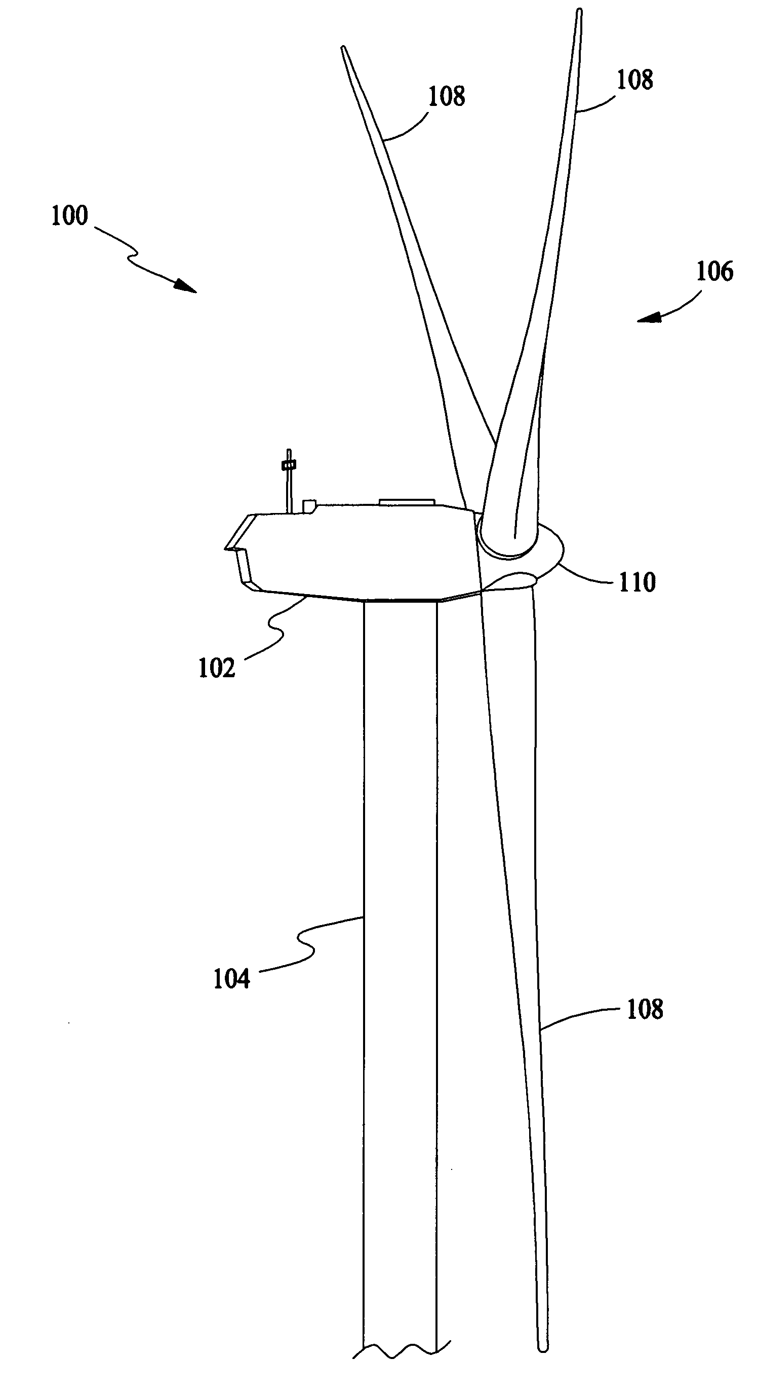
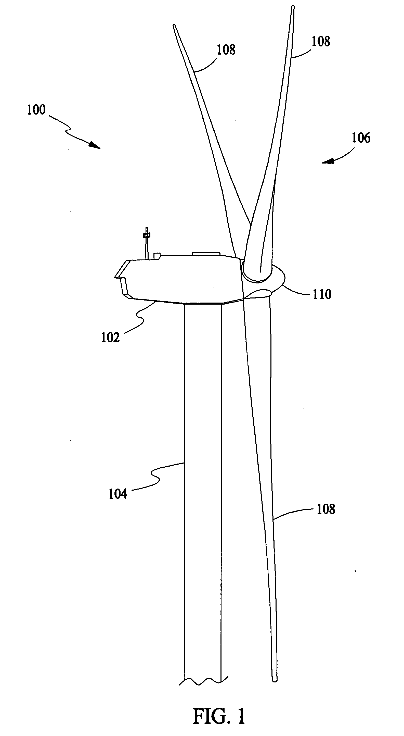
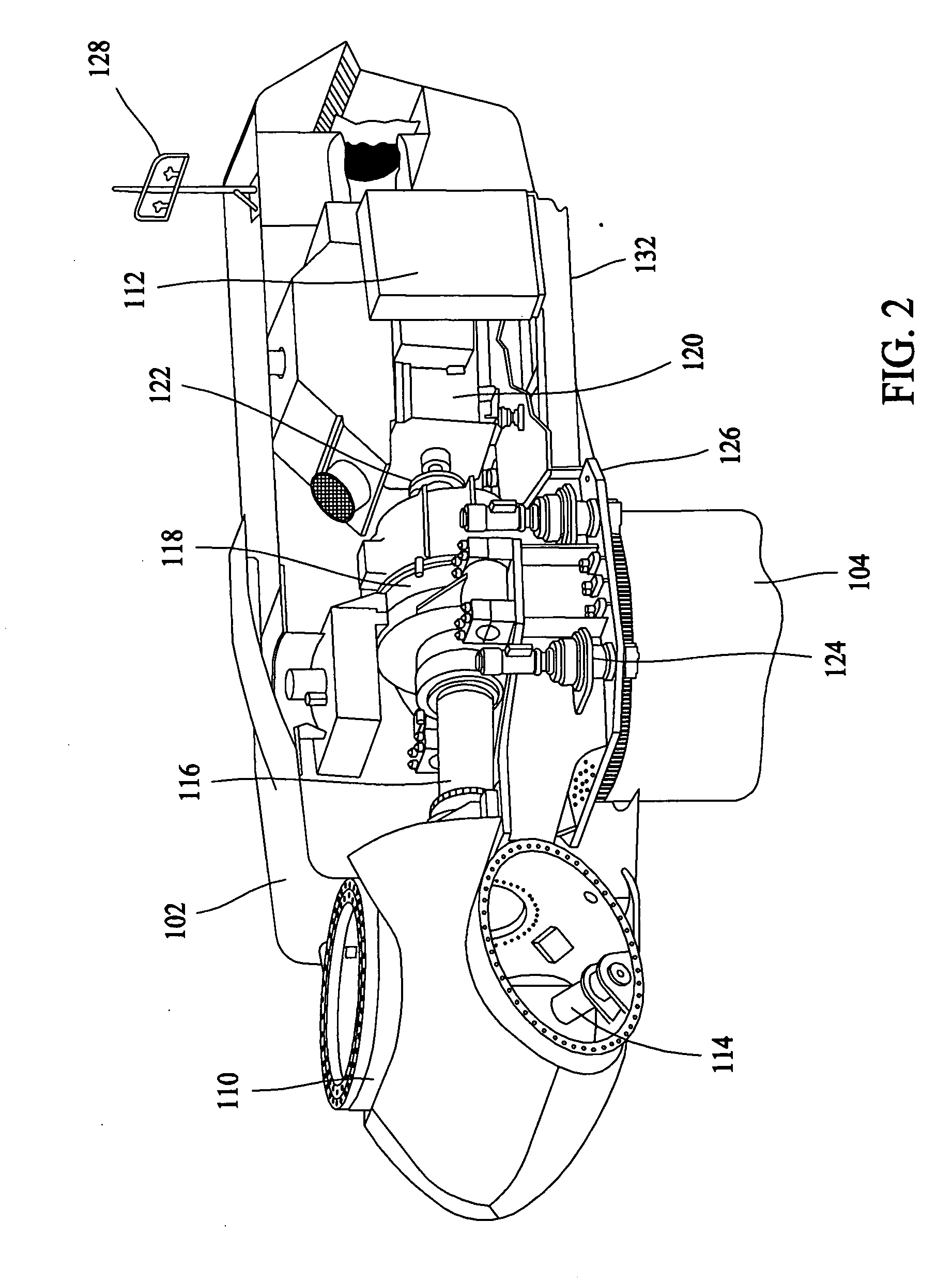
[0017] In various embodiments and referring to FIG. 1, a wind turbine system includes one or more wind turbines 100. The wind turbines 100 generally include a nacelle 102 housing a generator (not shown in FIG. 1). The nacelle 102 is mounted on a tower 104 (...


PUM


Abstract

A system and method for power control in wind turbines are provided. The method includes switching a plurality of switching devices in a power conversion component of the wind turbine system in a normal switching mode to provide power flow through the power conversion component. The method further includes switching the plurality of switches devices in the power conversion component of the wind turbine system in a short circuit switching mode to prevent power flow through the power conversion component.

Description

BACKGROUND OF THE INVENTION [0001] This invention relates generally to wind turbines, and more particularly, to systems for controlling power flow in wind turbines. [0002] Recently, wind turbines have received increased attention as an environmentally safe and relatively inexpensive alternative energy source. With this growing interest, considerable efforts have been made to develop wind turbines that are reliable and efficient. [0003] Generally, wind turbines use the wind to generate electricity. The wind turns multiple blades connected to a rotor. The spin of the blades caused by the wind spins a shaft of the rotor, which connects to a generator that generates electricity. Specifically, the rotor is mounted within a housing or nacelle, which is positioned on top of a truss or tubular tower. Utility grade wind turbines (e.g., wind turbines designed to provide electrical power to a utility grid) can have large rotors (e.g., 30 or more meters in diameter). Blades on these rotors tran...

Claims


Application Information

Patent Timeline
IPC IPC(8): F03D9/00H02P9/04
CPCF03D7/0272F03D7/028F03D9/003F05B2220/7062H02P2101/15F05B2270/1011H02P9/007Y02E10/723Y02E10/725F05B2260/80F03D9/25F03D9/255Y02E10/72
Inventor D'ATRE, JOHN DOUGLASKLODOWSKI, ANTHONY MICHAELRITTER, ALLEN MICHAELSMITH, DAVIDWAGONER, ROBERT GREGORYGARCES, LUIS JOSELUETZE, HENNING
Owner GENERAL ELECTRIC CO
Learn More