Disk alternator

a technology of alternators and disks, which is applied in the direction of dynamo-electric machines, electrical apparatus, magnetic circuits, etc., can solve the problems of increasing the weight of the generator, the loss of the generator, and the resistance force of the rotor rotation, etc., and achieves the effects of low cost, low cost and low cos

Inactive Publication Date: 2007-02-01
TECOBIM
View PDF25 Cites 38 Cited by
  • Summary
  • Abstract
  • Description
  • Claims
  • Application Information

AI Technical Summary

Benefits of technology

[0023] Thus, a preferred object of the present invention is to provide an alternator in which the axial magnetic flux of the rotor means is maintained at its maximum and the conductor looped on the surface of the stator means has no ferromagnetic core so as to reduce eddy currents and associated losses.
[0037] reduced maintenance cost based on simple assembly, and disassembly procedures.

Problems solved by technology

In order to be effective, the output rotation of such power plants must be increased by various mechanical means, representing an additional source of losses and maintenance requirements.
However, one drawback stems from the magnetically permeable armature core inside the stator coil: this magnetically permeable core exerts an attractive force on the magnetic rotor, causing a resistive force against the rotation of the rotor.
Moreover, the magnetically permeable material generally increases the weight of the generator and is a source of losses, owing to the heating, hysteresis and braking (cogging) of moving magnetic fields, all of which can actually reduce the current-generating efficiency of the alternator.
A drawback of this type of alternator stems from the magnetic flux return paths required between adjacent magnetic poles.
By adding “back-iron” to complete the magnetic circuit, the magnetic volume increases which increases hysteresis and eddy current losses (i.e. core losses) as well as the weight of the alternator thereby decreasing the power-generating efficiency.

Method used


Image

  • Disk alternator
  • Disk alternator
  • Disk alternator

Examples


Embodiment Construction

[0048] The present invention will be described more fully hereinafter with reference to the accompanying drawings, FIGS. 1 to 9, in which like numerals refer to like elements throughout.

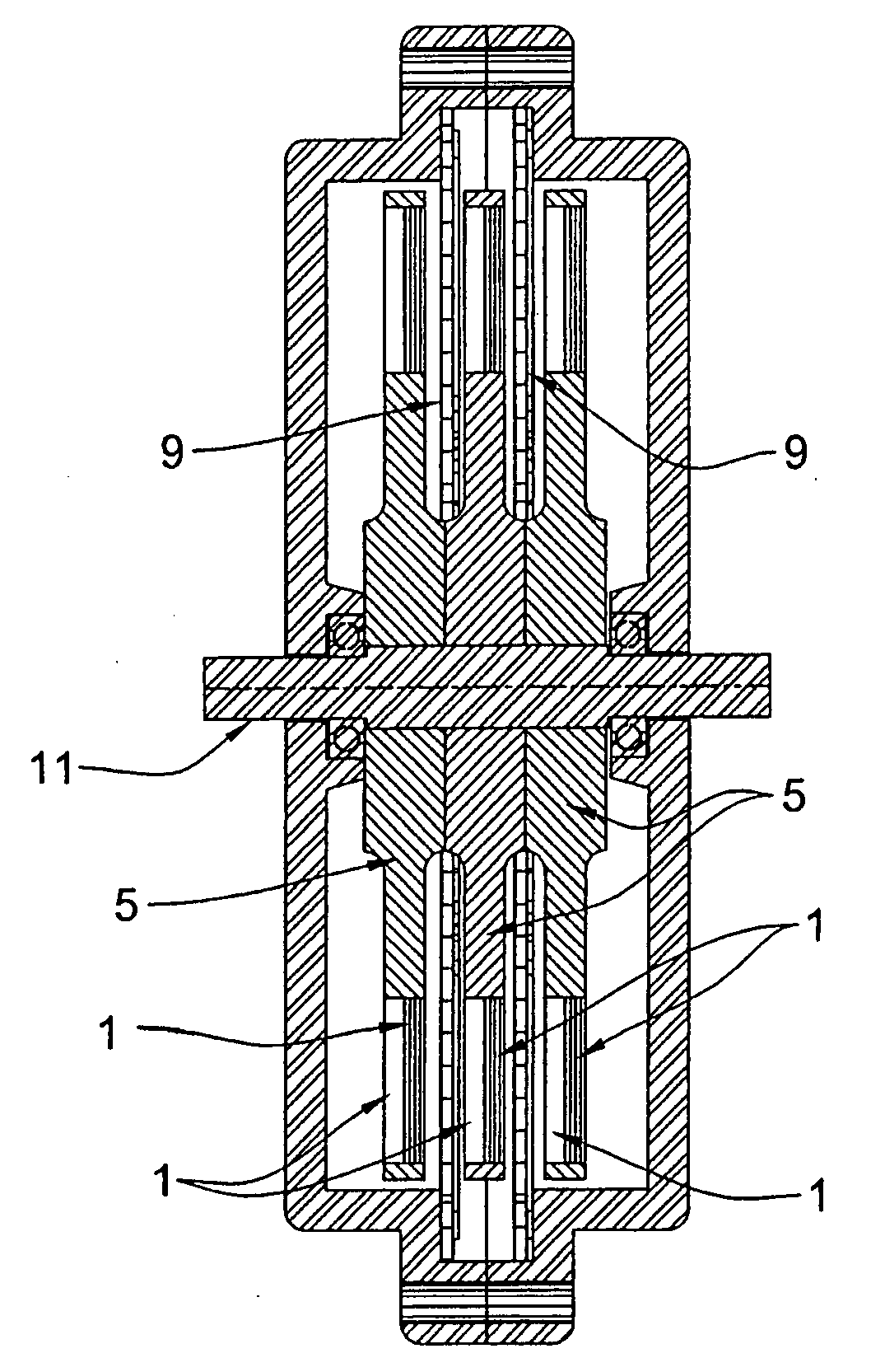
[0049] A disk alternator according to the present invention is an axial-gap rotary electric generator comprising rotor and stator means designed to be direct driven, thus eliminating the need for costly gearboxes.

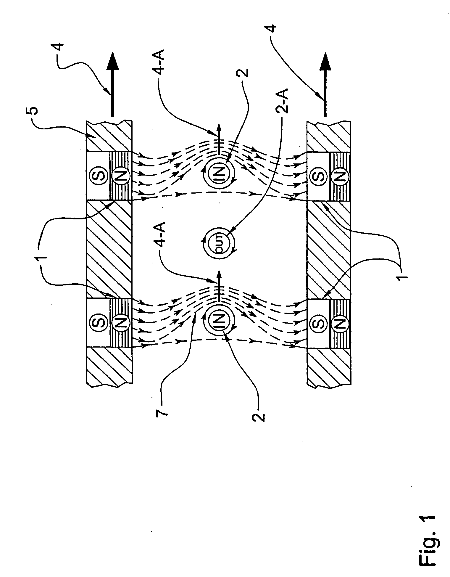
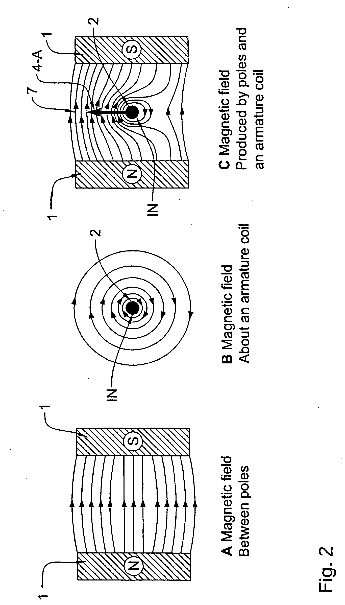
[0050] The rotor means comprises at least two rotating disks (i.e. disk rotors or rotor disks), each disk with a circular array of magnets arranged along the outer periphery in side-by-side relationship in a like polarity configuration. That is to say, the magnets of one disk are arranged side-by-side in a circular fashion with north (N) poles of the magnets disposed along the periphery of one surface of the rotor disk and south poles of the magnets disposed along the periphery of the opposite surface of the rotor disk. The disk rotors are “stacked” (i.e., arranged one over the other) keep...


PUM


Abstract

A power disk alternator includes a rotor of circular cross-section arranged to rotate about an axis having at least two disks facing each other and defining at least one gap therebetween, and a shaft connected to an external source for driving the shaft in rotation about the axis. Each disk has a circular array of arcuately-spaced magnetized elements located adjacent to its periphery, each of the magnetized elements having surfaces of opposite polarity and being disposed side-by-side in a like polarity configuration. Magnetized elements of one disk face magnetized elements of the other disk of opposite polarity, creating magnetic fields between the opposite polarities in the gap between the two disks. The alternator also includes a stator comprising at least one fixed nonmetallic disk having a conductor path comprising at least one uninterrupted conductor on at least one surface thereof, each stator being located in one of the at least one air gap. A connector is provided for connecting the conductor path to a load. When the external source drives the shaft in rotation, the rotor rotates, and the resulting rotating magnetic field induces a current in the conductor path.

Description

[0001] This application is a Continuation-in-part of U.S. patent application Ser. No. 10 / 911,867 filed on Aug. 5, 2004, which claims priority to Canadian Patent No. 2,436,369 filed on Aug. 5, 2003, and which application(s) are incorporated herein by reference.FIELD OF THE INVENTION [0002] The present invention relates generally to dynamoelectric machines, or generators, and more specifically to alternators having substantially ironless stator coils and permanent magnet rotors. BACKGROUND OF THE INVENTION [0003] Generator design is becoming increasingly important given continuously increasing demands for lightweight, durable and efficient generators capable of operating at low and high speeds for installations in windmills, diesel engines, reciprocating steam engines and many other similar power generators. [0004] An electric generator is a machine that transforms mechanical energy into electrical energy, i.e. motion into electric current. Basically, an electric generator uses Farada...

Claims


Application Information

Patent Timeline
Patent Type & Authority Applications(United States)
IPC IPC(8): H02K21/12H02K31/00H02K21/00H02K21/24
CPCH02K21/24
Inventor OBIDNIAK, LOUIS
Owner TECOBIM
Why Eureka
Try Eureka