Superconducting magnet configuration with switch

a superconducting magnet and configuration technology, applied in the direction of superconducting magnets/coils, measurement devices, instruments, etc., can solve the problems of easy destruction of superconducting switches, increased material requirements, and unstable wires, so as to achieve effective discharge of energy produced by quench

Inactive Publication Date: 2007-02-01
BRUKER BIOSPIN
View PDF14 Cites 11 Cited by
  • Summary
  • Abstract
  • Description
  • Claims
  • Application Information

AI Technical Summary

Benefits of technology

[0011] With the use of a normally conducting switch, the inventive magnet configuration is less susceptible to a quench and can be operated at higher currents. This is interesting, in particular, for high-performance magnets. The magnetic drift may also be effectively compensated for via the strength of the current fed by the mains supply and the predetermined ohmic resistance of the mechanically operable bridge.
[0022] The mechanically operable bridge can advantageously be replaced without heating the magnet coil. Operation of the magnet coil must therefore not be interrupted. A change and / or replacement of the resistance of the mechanically operable bridge can be realized in a simple fashion.

Problems solved by technology

This configuration is disadvantageous, since superconducting switches tend to immediately quench at high currents.
This can easily destroy the superconducting switch.
However, this increases the amount of material required.
These wires are, however, very unstable and are therefore suitable for the above-mentioned application only to a limited degree.

Method used


Image

  • Superconducting magnet configuration with switch
  • Superconducting magnet configuration with switch
  • Superconducting magnet configuration with switch

Examples


Embodiment Construction

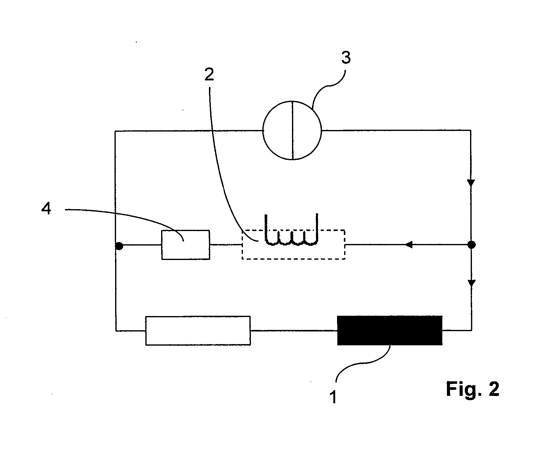
[0028]FIG. 2 shows a circuit of a conventional magnet configuration. A magnet coil 1 is connected in parallel with a superconducting switch 2 and a current source 3 which supplies the magnet coil 1 with a current IPS. The superconducting switch 3 remains open until the required magnetic field has been generated in the working volume. The magnet coil 1 can be short-circuited by closing the superconducting switch 2. When the switch 2 is closed, the current supply must remain connected. In order to minimize the magnetic field drift due to the intrinsic resistance of the magnet coil 1, the superconducting switch 2 is connected in series with a protective resistance 4, wherein the resistance 4 is much larger than the intrinsic resistance of the magnet coil 1. A voltage, which is exactly opposite to the voltage generated by the intrinsic resistance of the magnet coil, is generated at this protective resistance 4 by means of the current source 3, such that the algebraic sum of the circuit ...


PUM

PropertyMeasurementUnit
ohmic resistance R1aaaaaaaaaa
ohmic resistance RLaaaaaaaaaa

Abstract

A superconducting magnet configuration with a magnet coil (1) of inductance L which is disposed in a cryostat (7) at a cryogenic temperature, for generating a temporally stable magnetic field, in a working volume, which is suitable for NMR measurements, and with current feed lines to an external current source (3) via which a current of a current strength IPS can be supplied, wherein, at a cryogenic temperature, the magnet coil (1) can be exclusively short-circuited via a switch (5), is characterized in that the switch (5) is normally conducting and comprises a mechanically operable bridge (6) with an ohmic resistance R1 which can be predetermined. The inventive magnet configuration ensures straightforward stable permanent operation via a mains supply even at high currents (>1000A) and also effective discharge of the energy released during a quench.

Description

[0001] This application claims Paris Convention priority of DE 10 2005 034 837.8 filed Jul. 26, 2005 the complete disclosure of which is hereby incorporated by reference. BACKGROUND OF THE INVENTION [0002] The invention concerns a superconducting magnet configuration with a magnet coil of inductance L, which is disposed in a cryostat at a cryogenic temperature to generate a temporally stable magnetic field, in a working volume, suitable for NMR measurements, and with current feed lines to an external current source, via which a current of current strength IPS can be supplied, wherein the inductance at cryogenic temperatures can be exclusively short-circuited via a switch. [0003] A magnet configuration of this type is disclosed In DE 102 41 966. [0004] Superconducting magnet coils that generate a stable magnetic field are required for a plurality of applications in research and medicine, in particular for NMR apparatus. For this reason, the field drift of the magnet coil should be mi...

Claims


Application Information

Patent Timeline
Patent Type & Authority Applications(United States)
IPC IPC(8): H01F6/00
CPCH01F6/00H01F2006/001H01F6/02G01R33/3815
Inventor WESTPHAL, MICHAELRINGEISEN, VICTOR
Owner BRUKER BIOSPIN
Why Eureka
Try Eureka