
Apparatus and method for detection of liquid droplets

a technology of liquid droplets and apparatus, which is applied in the direction of printing, other printing apparatus, etc., can solve the problems of insufficient detection accuracy, inability to detect liquid droplets, etc., and achieve the effect of increasing the optical signal-to-noise ratio of the detector

Inactive Publication Date: 2007-02-01
EASTMAN KODAK CO
View PDF13 Cites 39 Cited by
  • Summary
  • Abstract
  • Description
  • Claims
  • Application Information

AI Technical Summary

Benefits of technology

[0008] An object of the present invention is to provide a method and apparatus to detect small volume ink drops with high signal to noise in order to efficiently detect the condition of ejection ports of an ink jet print head. In this case, efficiency refers to the use of time and ink with respect to the productivity of the printer. Such detection will enable the subsequent implementation of measures to maintain image quality. Measures to reactivate a non-functional or correct a malfunctioning ejection port may include spitting, purging, wiping, or other maintenance routines, or combinations thereof. In the event that maintenance routines fail to reactivate a non-functional or correct a malfunctioning ejection port, other methods can be employed to reduce or prevent degradation of the quality of the printed image such as using a redundant nozzle, or using a print mask that effectively hides the error.
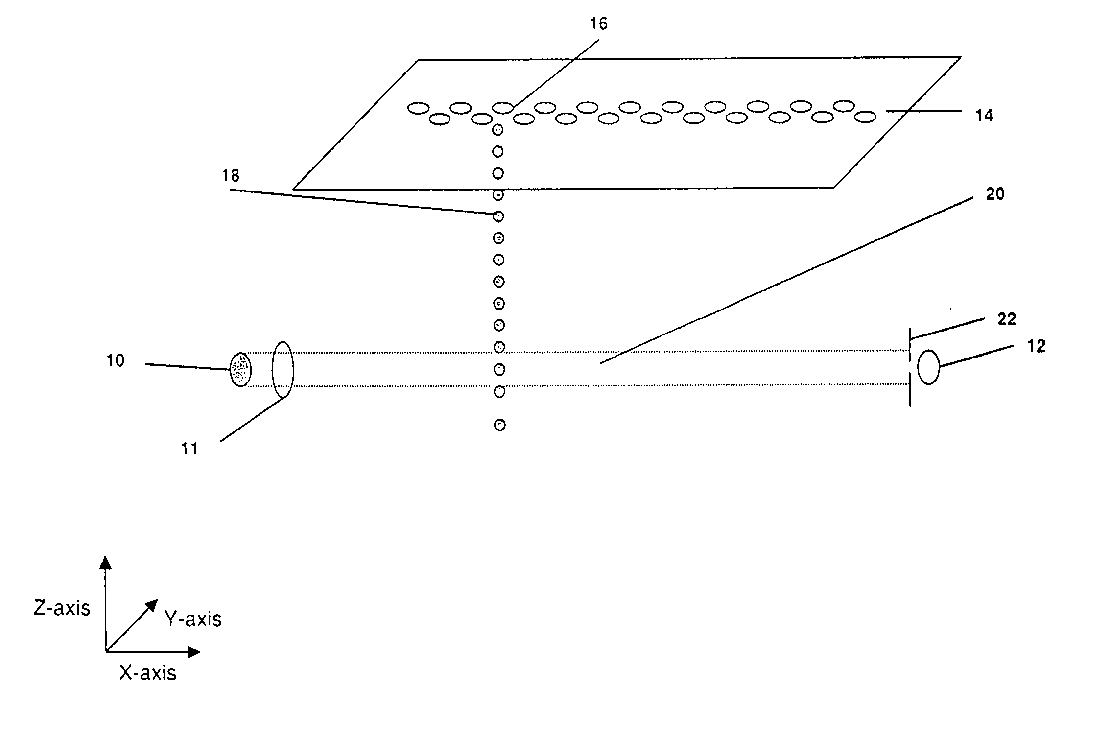
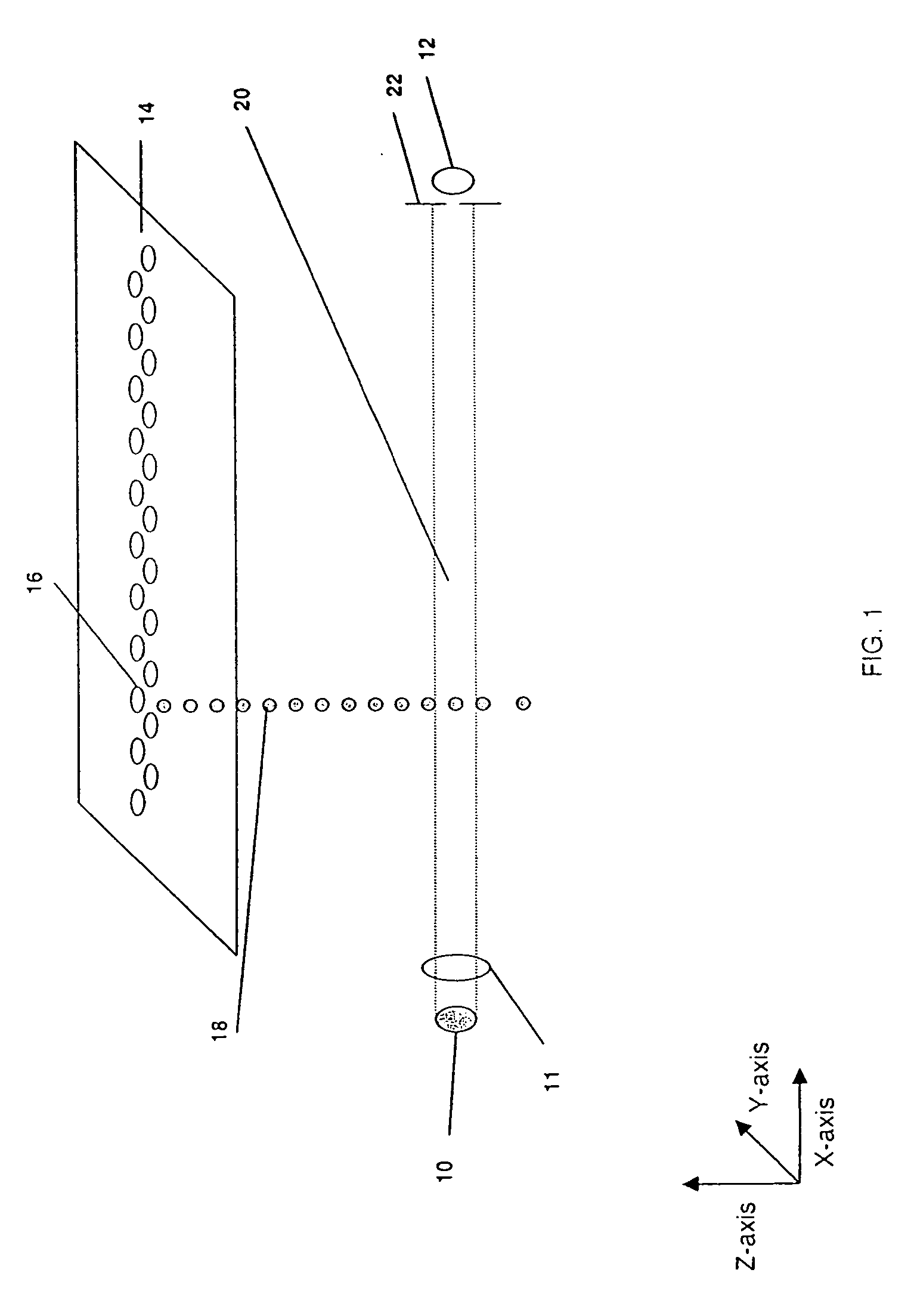
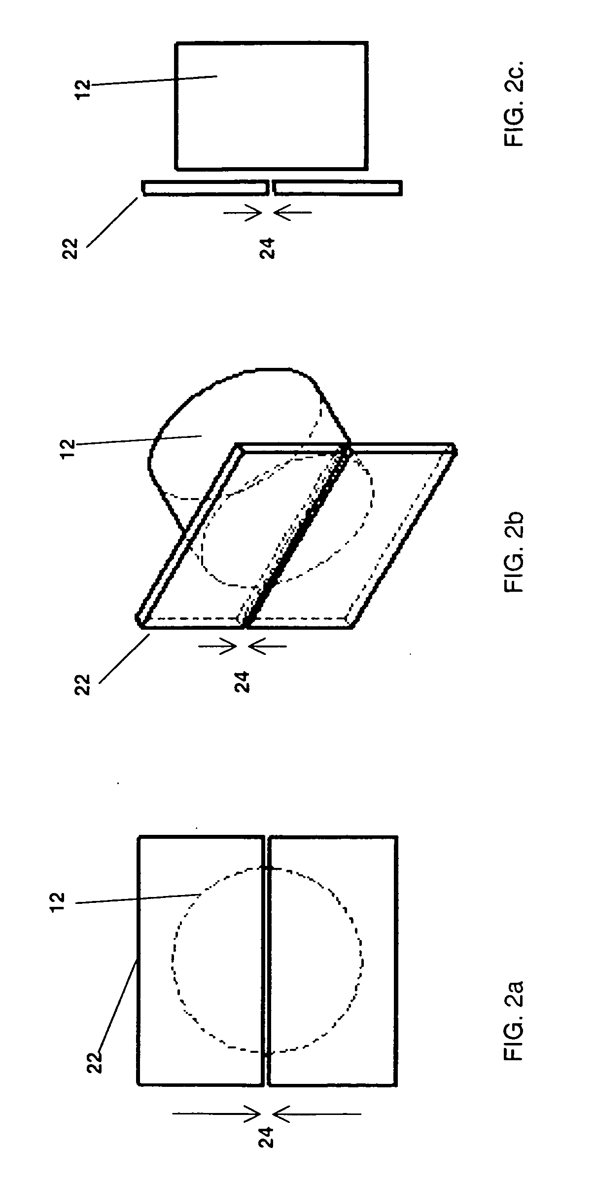
[0009] According to a first aspect of the present invention there is provided an ink jet printer comprising an ink jet print head having at least one row of a plurality of ink ejecting ports for ejecting ink droplets along a plurality of ink droplet paths, the ink jet print head residing at a first elevation; a collimated light source and a detector each residing at a second elevation that is lower than the first elevation, the detector positioned opposite the collimated light source, the ink jet print head being movable to a test position where the at least one row of a plurality of ink ejecting ports can fire non-printing droplets, the collimated light source directing light at the detector along a light path that intersects the plurality of ink droplet paths when the print head resides in the test position; and an aperture located in between the collimated light source and detector and proximate to the detector to limit a field of view of the detector and increase an optical signal-to-noise ratio of the detector. The increase in the optical signal-to-noise ratio of the detector allows for detection of ink droplets having a volume of as small as 1 picoliter.
[0012] According to a third aspect of the present invention there is provided a method for detecting liquid droplets fired from at least one ejector, the method comprising positioning the ejector at a test position; ejecting liquid droplets along at least one droplet path from the at least one ejector while the ejector is in the test position; directing collimated light toward a detector in a light path that intersects the at least one liquid droplet path; and restricting a field of view of the detector with an aperture proximately located to the detector thereby increasing an optical signal-to-noise ratio of the detector.

Problems solved by technology

However, ejection ports may malfunction for a variety of reasons.
For example, the nozzle plate may collect contaminants such as dust fibers over time.
These contaminants may adhere to the orifice plate either due to the presence of ink on the print head, or due to electrostatic charges.
In addition, excess ink may also accumulate and dry on the nozzle plate.
Ink, at the orifice of exposed ejection ports, may lose moisture if those ports are not utilized even for a short duration of time.
Factors such these interfere with the desired performance of some ejection ports causing ejected droplets to not have the desired physical characteristics.
Some poorly performing nozzles may eject ink droplets that have an incorrect volume, causing the dots produced on the page to be of an incorrect size.
Other mal-performing nozzles may eject drops with an improper velocity or trajectory, causing them to land at incorrect locations on the media.
Additionally, some mal-performing nozzles may completely fail to eject any ink droplets at all.
When such mal-performing nozzles are present, undesirable lines and banding artifacts will appear in the printed image, thereby degrading image quality.
Though such drop detection is clearly desirable to maintain image quality of the printer, the time required to perform the drop detection increases the total time required to print an image, thereby reducing productivity.

Method used


Image

  • Apparatus and method for detection of liquid droplets
  • Apparatus and method for detection of liquid droplets
  • Apparatus and method for detection of liquid droplets

Examples


Embodiment Construction

[0028] Inkjet print engines enable printing via ejection of droplets of ink from ejection ports or nozzles onto a desired receiver. In order to maximize printing efficiency and image quality, it is critical to assess the performance of these ejection ports. This can be achieved by monitoring the characteristics of the ejected drops. For example, the absence of a drop could indicate a failure to fire the ejector or need for servicing. Another example that could indicate poor performance of the particular ejector is low velocity for an ejected drop.

[0029] The present invention employs optical drop detection. A path of light, also referred to as the detection zone, is produced with a suitable emitter or light source and directed to impinge upon a detector. A row of ejector ports is aligned substantially parallel to this path of light such that the ejected drops pass through and intercept the path of light. The momentary partial obstruction of light is detected, thereby achieving detec...


PUM


Abstract

An ink jet printer comprising an ink jet print head having at least one row of a plurality of ink ejecting ports for ejecting ink droplets along a plurality of ink droplet paths, the ink jet print head residing at a first elevation; a collimated light source and a detector each residing at a second elevation that is lower than the first elevation, the detector positioned opposite the collimated light source, the ink jet print head being movable to a test position where the at least one row of a plurality of ink ejecting ports can fire non-printing droplets, the collimated light source directing light at the detector along a light path that intersects the plurality of ink droplet paths when the print head resides in the test position; and an aperture located in between the collimated light source and detector and proximate to the detector to limit a field of view of the detector and increase an optical signal-to-noise ratio of the detector.

Description

FIELD OF THE INVENTION [0001] The present invention relates generally to monitoring the performance of liquid ejection ports, and more particularly, to an apparatus and method for monitoring the performance of ink ejection ports in ink jet printers. BACKGROUND OF THE INVENTION [0002] An ink jet printer produces images on a receiver by ejecting ink droplets onto the receiver. The receiver is the media (e.g., paper, fabric, etc.) on which the printing is performed. Ink jet printing devices, (e.g., printers, photocopiers, facsimile machines, etc.), typically house a print head with ejection ports, often referred to as nozzles, that fire drops of ink onto a receiver. The advantages of non-impact, low-noise, low energy use, and low cost of operation, in addition to the capability of the printer to print on plain paper, are largely responsible for the wide acceptance of ink jet printers in the marketplace. [0003] Ink jet print heads include ejection ports on a nozzle plate through which t...

Claims


Application Information

Patent Timeline
Patent Type & Authority Applications(United States)
IPC IPC(8): B41J29/393
CPCB41J2/2142
Inventor DIOL, SABRINA J.FERSCHL, MICHAEL S.KIRCHER, JAMES R.
Owner EASTMAN KODAK CO
Learn More