Eureka AIR delivers breakthrough ideas for toughest innovation challenges, trusted by R&D personnel around the world.

Relevant image detection in a camera, recorder, or video streaming device

a technology of video streaming device and camera, applied in the field of video monitoring system, can solve the problems of ineffective environment of conventional motion-based filtering techniques, inconvenient use of motion-based filtering techniques, so as to reduce the amount of video processing or video analysis, and reduce the bandwidth requirements of video monitoring system

Active Publication Date: 2007-02-01
HONEYWELL INT INC
View PDF4 Cites 69 Cited by
  • Summary
  • Abstract
  • Description
  • Claims
  • Application Information

AI Technical Summary

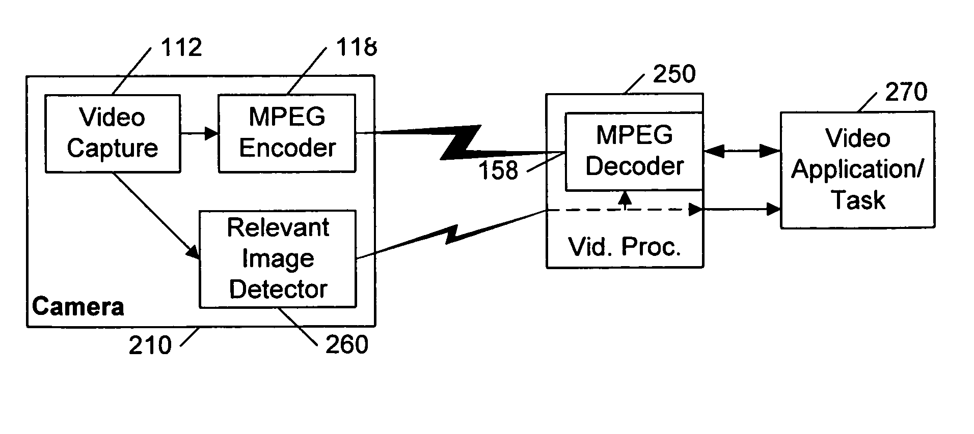
Benefits of technology

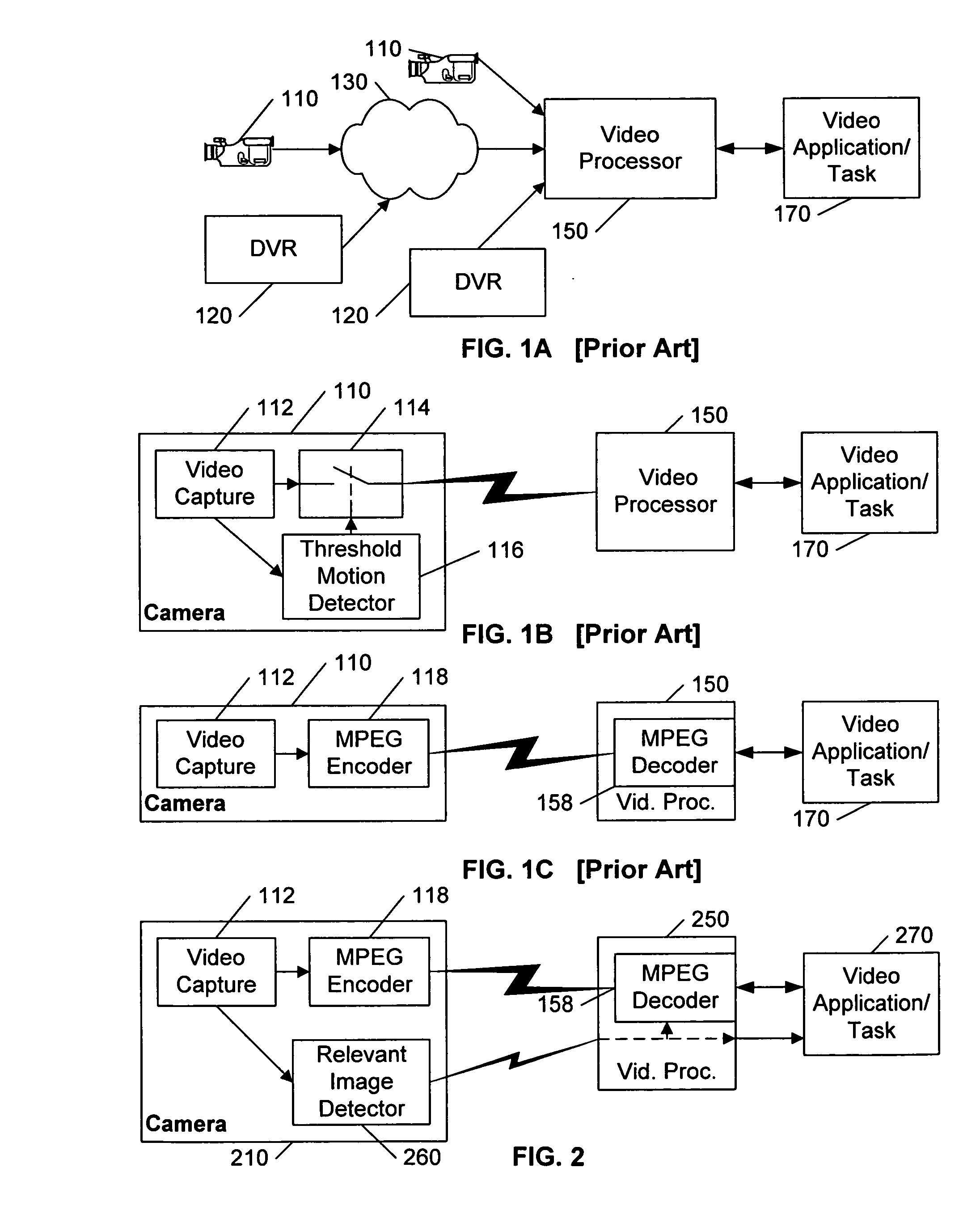
[0007]FIG. 1B illustrates a block diagram of a Dickinson-like technique in the context of this invention. The camera 110 includes a video capture component 112 that sequentially captures images, and a motion detector 116 that determines whether the amount of change / motion in the sequence exceeds a given threshold. The motion detector controls a switch 114 that selectively couples the video images from the video capture component 112 to the output of the camera, based on whether the threshold is exceeded. In this manner, only images that exhibit at least a minimum amount of change / motion are communicated to the video processor 150. This technique is particularly effective for minimizing traffic on a limited bandwidth video network that may be coupled to a plurality of video sources, such as illustrated in FIG. 1A. That is, if each of the cameras 110 and the DVR 120 of FIG. 1A are configured to only transmit changes that exceed a given threshold to the processor 150, the bandwidth of the channel used to route the video from each source 110, 120 to the video processor can be substantially reduced, compared to a continuous video stream from each of the sources 110, 120.
[0011] An object of this invention is to provide a video monitoring system that is well structured for multiple-camera operations. A further object of this invention is to provide a video monitoring system that is well suited for environments that exhibit activity / motion that is generally unrelated to the video monitoring application. A further object of this invention is to provide a video monitoring system that reduces the amount of video processing or video analysis required to perform a given task. A further object of this invention is to further reduce the bandwidth requirements for video monitoring systems.
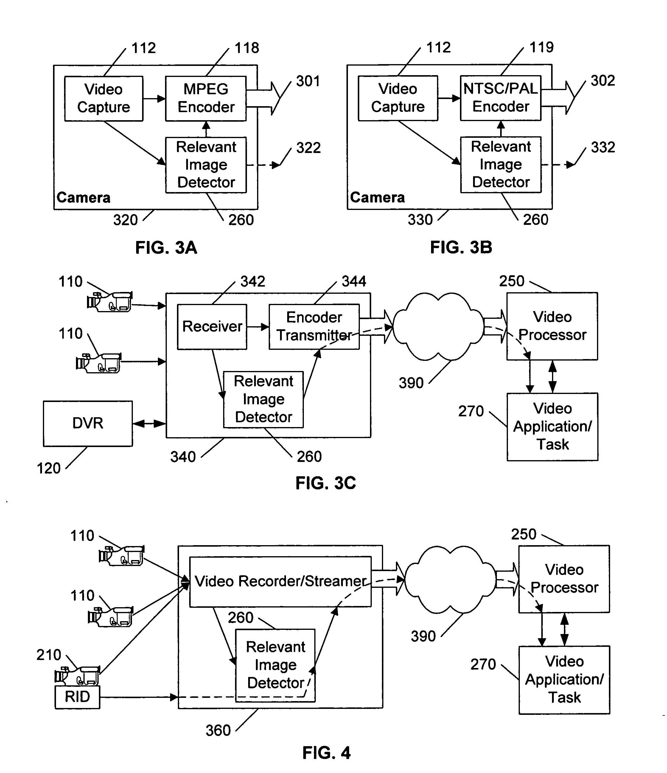
[0012] These objects, and others, are achieved by distributing the video processing typically performed in a video monitoring system among the components of the system. Specifically, the filtering tasks that are conventionally applied in a video monitoring application, to identify activity in the images that may be relevant to the monitoring task, are distributed to the image source, or near-source devices. Source devices, such as cameras and playback devices, and near-source devices, such as video concentrators and streaming devices, are configured to include video processing tools that can be used to pre-filter the image data to identify frames or segments of frames that include information that is likely to be relevant to the receiving video monitoring application. In this manner, the receiving processor need not spend time and resources processing images that are pre-determined to be irrelevant to the receiving application.

Problems solved by technology

That is, minor changes consume minor amounts of bandwidth, whereas fuller or more complex changes consume substantially more bandwidth.
A further problem with the motion-based filtering approaches of FIGS. 1B and 1C relates to the indiscriminate nature of motion-detection.
That is, conventional motion-based filtering techniques are fairly ineffective in environments that are expected to exhibit movements that are irrelevant to the task at hand, and are generally only effective in limited environments, such as systems that monitor the interior of bank safes, or office or factory environments during ‘off-hours’, and so on.

Method used


Image

  • Relevant image detection in a camera, recorder, or video streaming device
  • Relevant image detection in a camera, recorder, or video streaming device
  • Relevant image detection in a camera, recorder, or video streaming device

Examples


Embodiment Construction

[0019] In the following description, for purposes of explanation rather than limitation, specific details are set forth such as the particular architecture, interfaces, techniques, etc., in order to provide a thorough understanding of the concepts of the invention. However, it will be apparent to those skilled in the art that the present invention may be practiced in other embodiments, which depart from these specific details. In like manner, the text of this description is directed to the example embodiments as illustrated in the Figures, and is not intended to limit the claimed invention beyond the limits expressly included in the claims. For purposes of simplicity and clarity, detailed descriptions of well-known devices, circuits, and methods are omitted so as not to obscure the description of the present invention with unnecessary detail. In like manner, the examples are provided using labels and terminology that are easily recognized, to facilitate understanding. For example, t...


PUM


Abstract

The filtering tasks that are conventionally applied in a video monitoring application, to distinguish images that may be relevant to the application, are distributed to the image source, or near-source devices. Source devices, such as cameras and playback devices, and near-source devices, such as video concentrators and streaming devices, are configured to include video processing tools that can be used to pre-filter the image data to identify frames or segments of frames that include image information that is likely to be relevant to the receiving video monitoring application. In this manner, the receiving processor need not spend time and resources processing images that are pre-determined to be irrelevant to the receiving application.

Description

[0001] This application claims the benefit of U.S. Provisional Patent Application 60 / 668,446, filed 5 Apr. 2005.BACKGROUND AND SUMMARY OF THE INVENTION [0002] This invention relates to the field of video systems, and in particular to video input devices that include processes for identifying motion in a video image that is relevant to a given video processing task. [0003] The application of video image processing to varieties of tasks continues to grow. Such applications include, for example, video surveillance, inventory control, traffic management, and so on. [0004]FIG. 1 illustrates a typical image-based system. A video processor 150 receives video image data from a variety of image sources 110, 120. The image source may be, for example, a video camera 110 that provides ‘live’ images, or a video recorder 120 that provides previously captured images. The sources 110, 120 may be connected directly to the processor 150, or via a network 130, or a combination of both. [0005] The vide...

Claims


Application Information

Patent Timeline
Patent Type & Authority Applications(United States)
IPC IPC(8): H04N7/18
CPCG06K9/00771G08B13/1961G08B13/19645H04N5/232G08B13/19669G11B27/28G08B13/19663G06V20/52H04N23/60H04N19/463G06V20/40
Inventor BRODSKY, TOMAS
Owner HONEYWELL INT INC
Why Eureka
Eureka Blog
Learn More