Ophthalmic device lateral positioning system and associated methods

Inactive Publication Date: 2007-02-01
ALCON REFRACTIVEHORIZONS
View PDF2 Cites 17 Cited by
  • Summary
  • Abstract
  • Description
  • Claims
  • Application Information

AI Technical Summary

Benefits of technology

[0009] Embodiments of the system and method of the present invention have an advantage that no additional hardware is required if the ophthalmic device already comprises means for imaging the surface of the eye and for capturing that image. An additional element can comprise a software package for computing optimal centering and focal position, and for either driving the ophthalmic device position or for indicating a required ophthalmic device movement, depending upon the presence of an automatic positioning capability.

Problems solved by technology

Known current approaches to solving the positioning problem are typically subject to error and require intervention by an operator and / or additional hardware.

Method used


Image

  • Ophthalmic device lateral positioning system and associated methods
  • Ophthalmic device lateral positioning system and associated methods
  • Ophthalmic device lateral positioning system and associated methods

Examples


Embodiment Construction

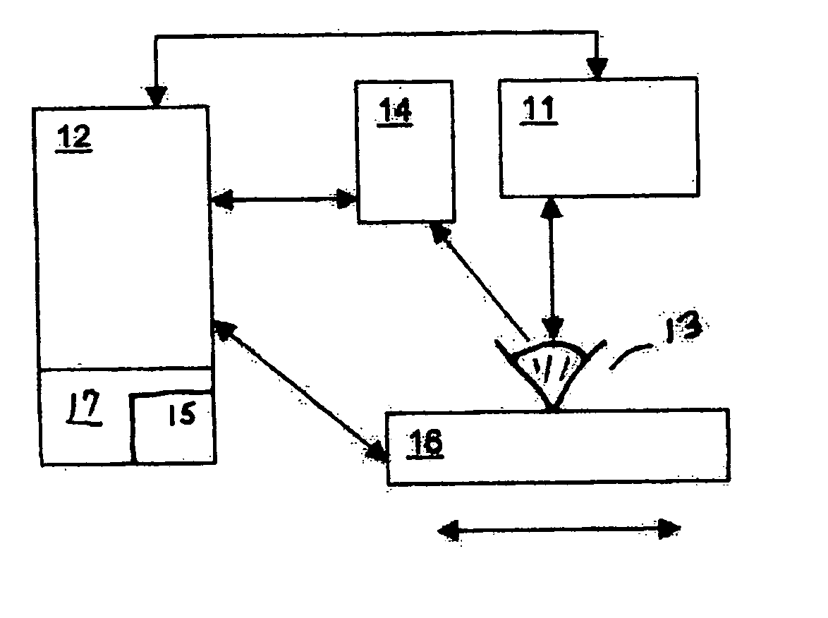
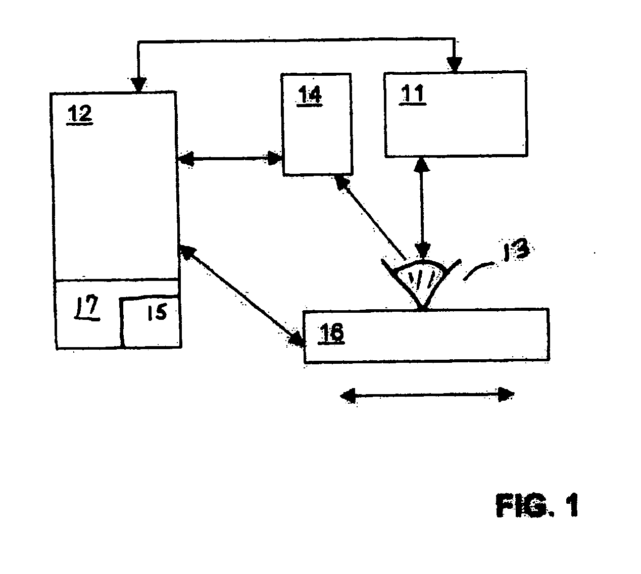
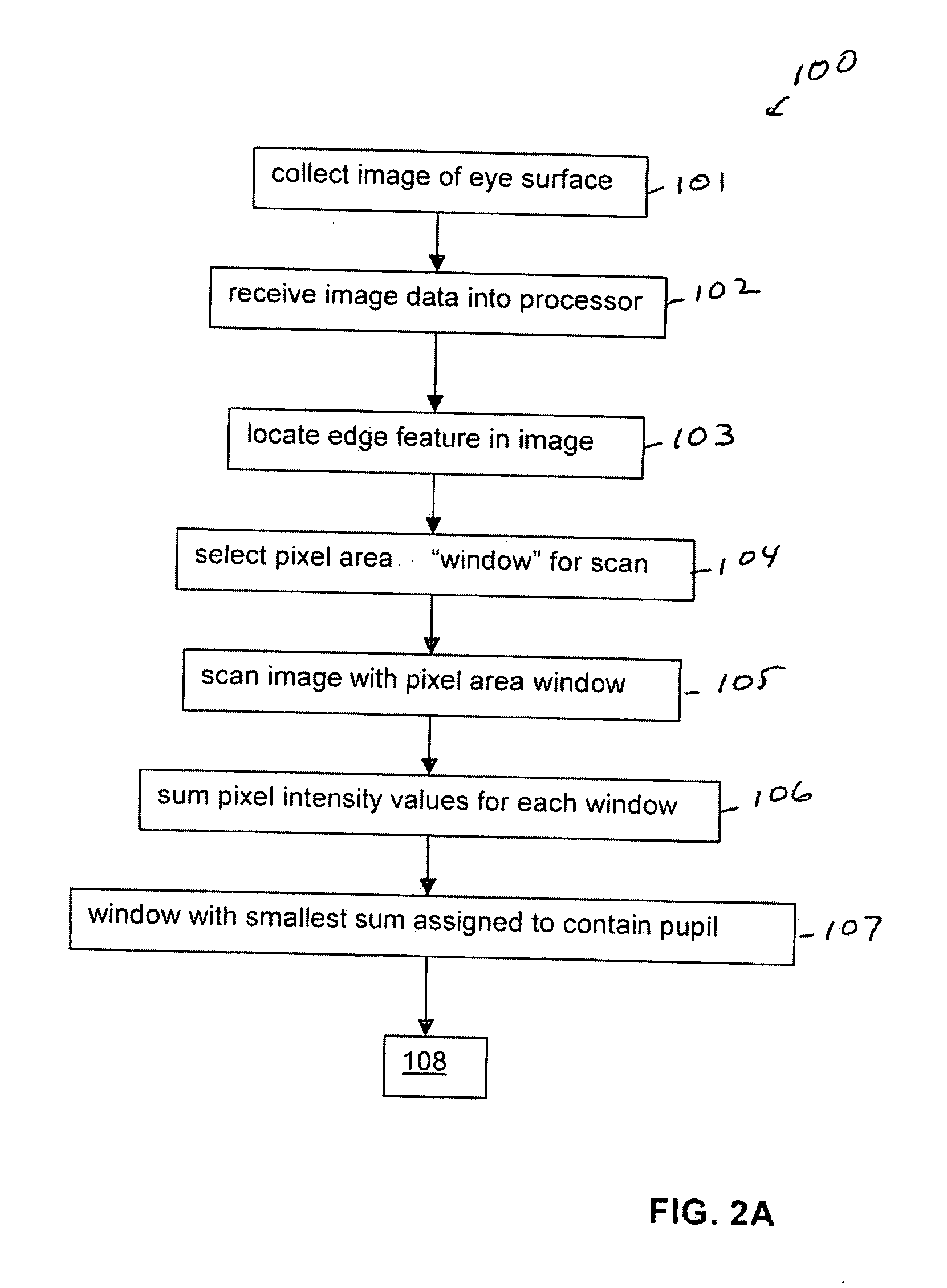
[0016] A description of the preferred embodiments of the present invention will now be presented with reference to FIGS. 1-4. An exemplary eye positioning system 10 is depicted schematically in FIG. 1, and an exemplary method 100, in FIGS. 2a and 2b.

[0017] An embodiment 100 of the method for determining an optimal position of an eye 13 relative to an ophthalmic device 11 comprises the step of receiving data into a processor 12 (block 102). The data comprise an image of a surface of an eye 13 that has been collected (block 101) with, for example, a video camera, digital camera, still camera or frame grabber 14, in communication with the processor 12. The image is collected with the eye at a first position relative to the ophthalmic device 11 (block 101), and typically comprises a plurality of pixels, with each pixel having an intensity value associated therewith. Ophthalmic device 11 can be, for example, and without limitation, a femtosecond laser microkeratome, a treatment laser, s...


PUM


Abstract

A system and method for determining a lateral position of an eye relative to an ophthalmic device are disclosed. One embodiment of the method includes receiving data comprising an image of a surface of an eye. An edge feature in the image is located, wherein the edge feature is in a known relationship to a pupil of the eye. The image is mapped from the edge feature to laterally define the pupil, and a center of the pupil is determined using the pupil definition. The pupil center comprises a location from which to achieve a preferred lateral eye position relative to an ophthalmic device. An embodiment of the system of this invention can include a processor and a software package executable by the processor, the software package adapted to cause the processor to carry out the method steps.

Description

CROSS-REFERENCE TO RELATED APPLICATIONS [0001] This application claims priority under 35 U.S.C. §119 to U.S. Provisional Patent Application No. 60 / 703,669, filed Jul. 29, 2005, the entire contents of which are incorporated herein by reference.TECHNICAL FIELD OF THE INVENTION [0002] The present invention relates to systems and methods for performing corneal wavefront measurements and laser-assisted corneal surgery, and, more particularly, to such systems and methods for optimizing a lateral positioning of the eye undergoing such surgery. BACKGROUND OF THE INVENTION [0003] It is known in the art to perform corneal ablation by means of wavefront-guided refractive laser surgery. Typically a wavefront sensor measures the aberrations in an eye to produce an aberration map and determines its position relative to anatomical landmarks, which can be intrinsic or externally applied features. Aberration data, sometimes along with geometric registration information, can be transferred directly t...

Claims


Application Information

Patent Timeline
IPC IPC(8): A61B3/14
CPCA61B3/14A61B3/145A61F2009/00872A61F9/007A61F9/008A61B3/152A61B3/10
Inventor CAMPIN, JOHN A.BOWES, JOHN J.
Owner ALCON REFRACTIVEHORIZONS
Why Eureka
Try Eureka