Microscope Having A Surgical Slit Lamp Having A Laser Light Source

a laser light source and microscope technology, applied in the field of microscopes with slit lamps, can solve the problems of undesirable bulky structures at this mounting location, the overall handling of the surgical microscope, and the large volume of the lamp housing

Inactive Publication Date: 2007-02-01
LEICA INSTR SINGAPORE PTE
View PDF4 Cites 29 Cited by
  • Summary
  • Abstract
  • Description
  • Claims
  • Application Information

AI Technical Summary

Benefits of technology

[0023] A further preferred variant embodiment of a microscope having an illumination apparatus according to the present invention provides for the illumination apparatus to be removable. This makes it possible selectably to effect illumination with a modulated (modified) light-beam bundle, or instead to provide an (additional) conventional microscope illumination system at that mounting location.
[0024] Within the scope of the invention, the light modulator can certainly be embodied to generate a predetermined shape of the light-beam bundle, i.e., for example, to generate slit light, ring light, or also a central illuminated field. It is preferred, however, if the light modulator is controllable by way of an electronic control unit coupled to it, so that structures varying over time can be generated, for example with the aid of a computer or another control unit. With computer-assisted control of the light modulator, the shape and size (height, width) of the illuminated field can be varied. This control of the light modulator also offers the possibility of switching in freely selectable fashion back and forth between different aforesaid illuminated-field shapes.

Problems solved by technology

The lamp housings of these surgical slit lamps are very bulky, however, because of the light source incorporated thereinto, which is usually a halogen lamp.
Bulky structures at this mounting location are undesirable, however, because they reduce the open working distance and are thus disadvantageous for the overall handling of the surgical microscope.

Method used


Image

  • Microscope Having A Surgical Slit Lamp Having A Laser Light Source
  • Microscope Having A Surgical Slit Lamp Having A Laser Light Source
  • Microscope Having A Surgical Slit Lamp Having A Laser Light Source

Examples


Embodiment Construction

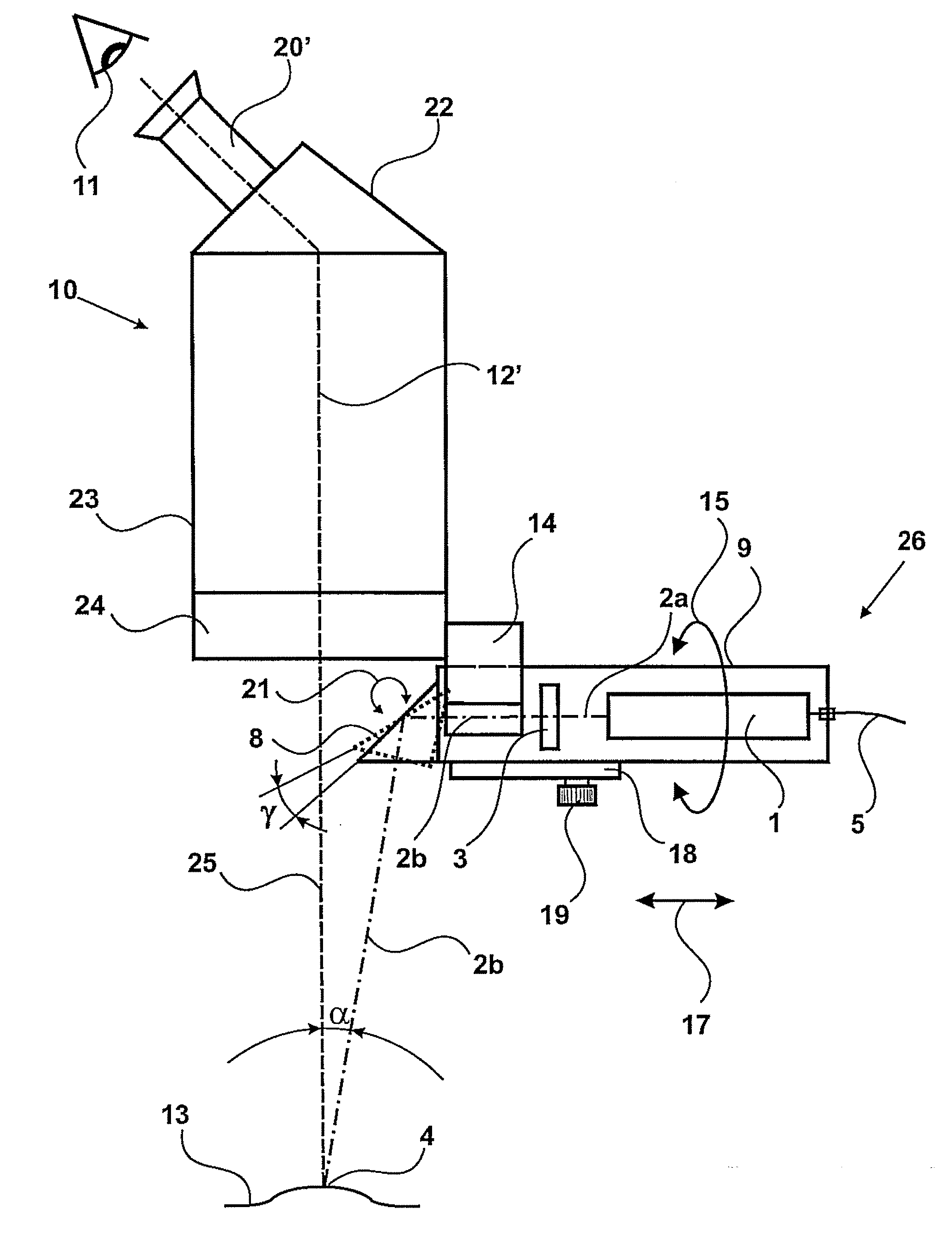
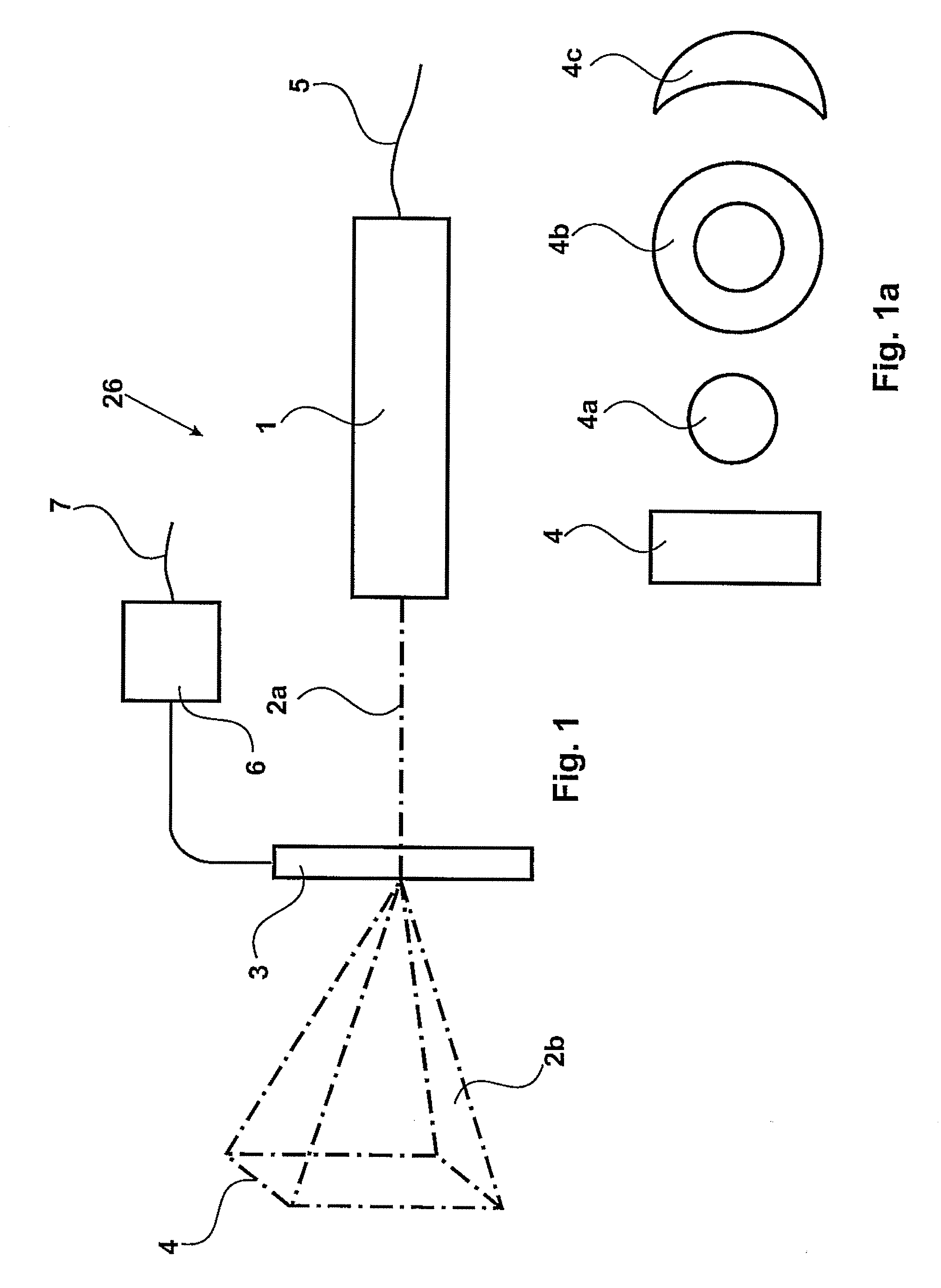
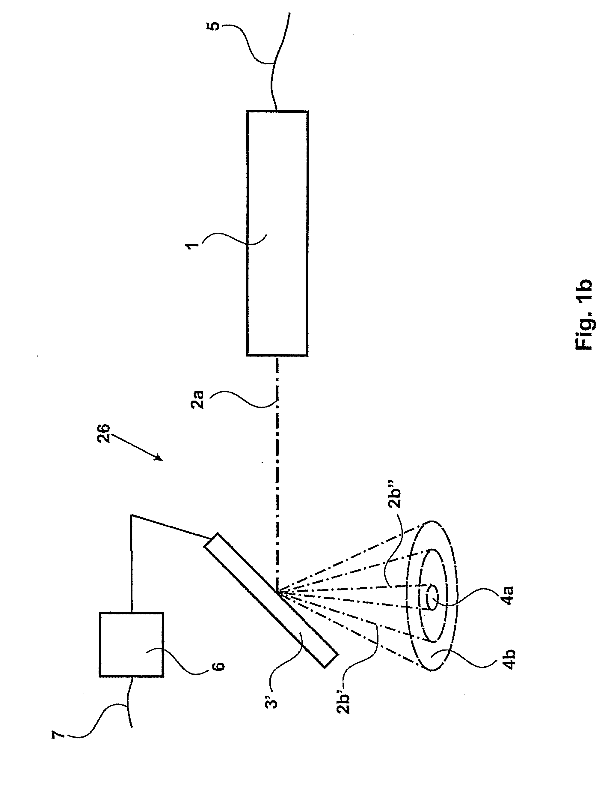
[0037]FIG. 1 schematically depicts an illumination apparatus 26 according to the present invention in which a conventional light source, such as an incandescent bulb, a halogen lamp, or the like, is replaced by a light source for the output of coherent light. In a preferred embodiment, this light source for coherent light is a laser diode 1 that is powered from an electrical energy source (not depicted) via an electrical supply lead 5.

[0038] The wavelength of this laser diode 1 can be selected in accordance with requirements, but there are also laser diodes that can be excited to output laser light of selectably different wavelengths. For retinal surgery, it will be preferable to select a laser diode 1 that emits red light. It should be mentioned that many laser diodes do not emit entirely coherent light; but a light of this kind is still to be regarded, in the context of the present description, as being embraced by the term “coherent.” In addition, the output of laser diode 1 can...


PUM


Abstract

The invention relates to a microscope (10) having an illumination apparatus (26) having a light source (1) and an optical system. The light source (1) is embodied to output a coherent light beam bundle along a defined illumination beam path (2a), and the optical system in the illumination beam path (2a) encompasses a spatial light modulator (3) for modifying the illuminated field (4). A surgical microscope (10) is preferably equipped with an illumination apparatus (26) of this kind that is arranged adjustably in two directions on the surgical microscope (10).

Description

CROSS REFERENCE TO RELATED APPLICATIONS [0001] This application claims priority of the German patent application no. 10 2005 034 829.7 filed Jul. 26, 2005, which is incorporated by reference herein. FIELD OF THE INVENTION [0002] The invention relates to a microscope having a slit lamp that is used in ophthalmology for surgery and diagnosis. BACKGROUND OF THE INVENTION [0003] A slit lamp is generally understood to be an illumination apparatus that is used to view the front portion of the eye (lens and proximal vitreous body, and for inspection when fitting contact lenses). With the aid of the slit image, structures and layers in the eye can be better recognized during diagnostic and surgical procedures. Surgical slit lamps are used for the most part in combination with a surgical microscope in intraocular and especially in retinal surgery. By means of the rectangular illuminated field on the retina, membranes that have become diseased, which are very thin but nevertheless greatly red...

Claims


Application Information

Patent Timeline
Patent Type & Authority Applications(United States)
IPC IPC(8): G02B21/06A61B18/18G02B21/00G02B21/18A61B3/10
CPCA61B3/135G02B21/06G02B21/0004A61B19/5223A61B90/20
Inventor SANDER, ULRICH
Owner LEICA INSTR SINGAPORE PTE
Why Eureka
Try Eureka