Bearing for axially mounting a rotor of a gas turbine, and gas turbine

a technology for gas turbines and rotors, which is applied in the direction of sliding contact bearings, mechanical equipment, machines/engines, etc., can solve the problems of low and thus non-damaging displacement speed of rotors, and achieve the effect of specific shutdown of gas turbines, uniform force distribution, and optimized force transmission

Inactive Publication Date: 2007-02-01
SIEMENS AG
View PDF10 Cites 7 Cited by
  • Summary
  • Abstract
  • Description
  • Claims
  • Application Information

AI Technical Summary

Benefits of technology

[0016] According to a special advantage of the invention, the piston chambers are fluidically connected to one another. This advantageously achieves a pressure balance between the individual piston chambers, thereby achieving, firstly, a uniform load distribution, but also, secondly, a uniformly rectilinear displacement of the rotor of the gas turbine. The individual piston chambers may in this case be fluidically connected to a common pressure space via appropriately designed bores or else may be fluidically connected to one another directly via appropriately designed bores. It is crucial that a pressure balance can be effected between the individual piston chambers.
[0017] According to a further feature of the invention, the hydraulic piston arrangement is of annular design and surrounds the rotor, of circular design in cross section, of the gas turbine. For optimized transmission of force from the hydraulic pistons to the rotor, the pistons are arranged equidistantly from one another with respect to the hydraulic piston arrangement of annular design, so that a uniform force distribution can be achieved. Depending on the configuration and size of the hydraulic piston arrangement of annular design, the common pressure space connecting the piston chambers to one another may likewise be of annular design and may surround the hydraulic piston arrangement.
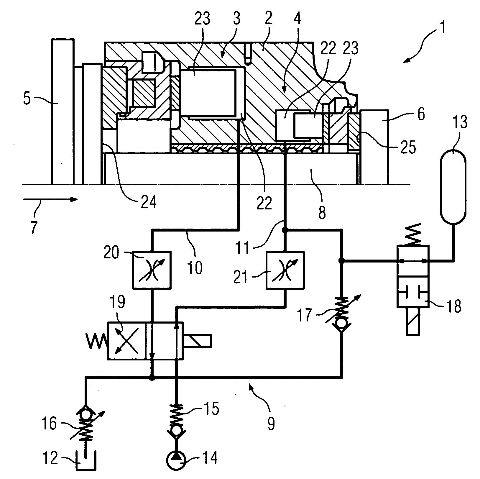
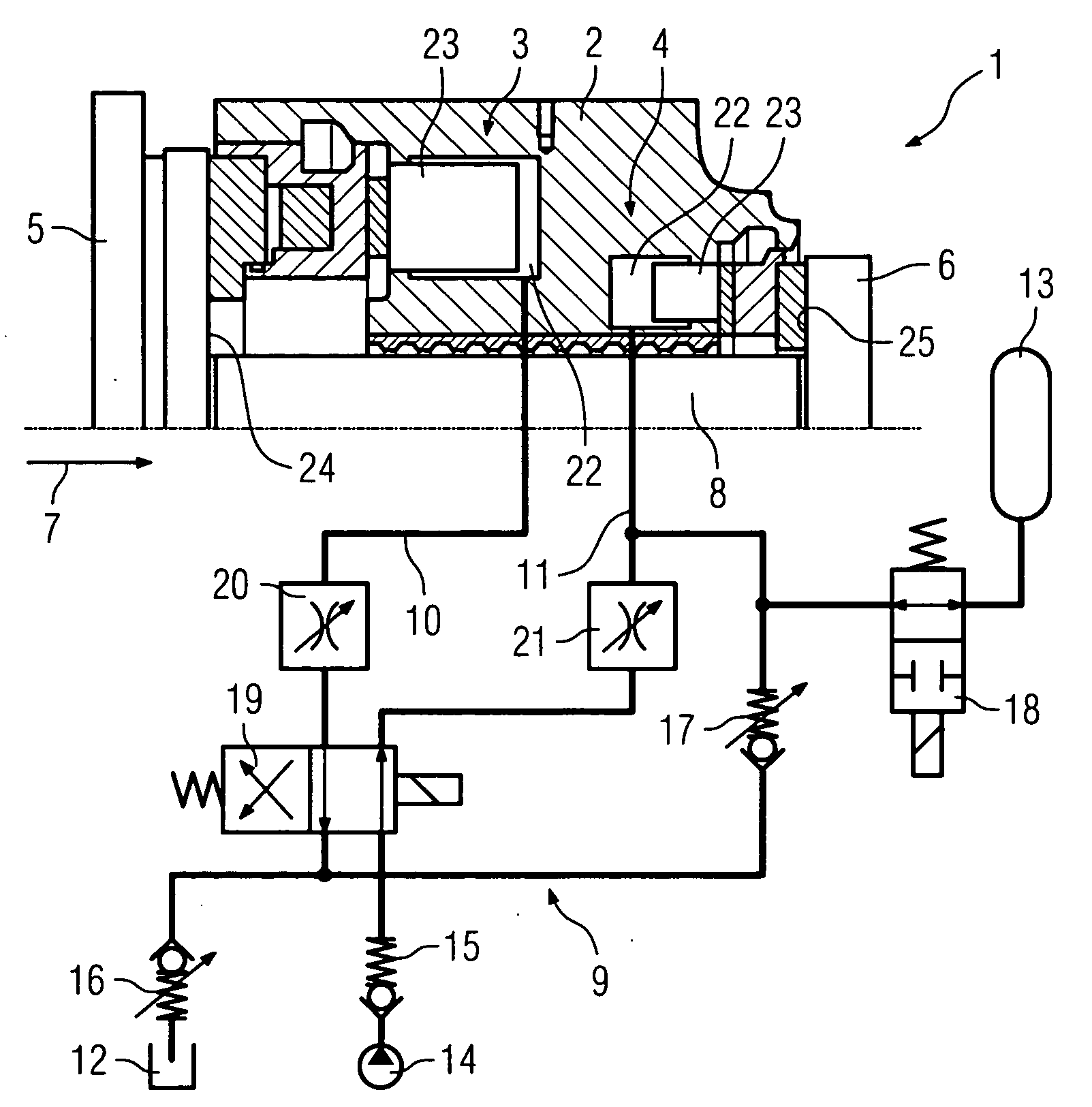
[0018] According to a further feature of the invention, two hydraulic piston arrangements formed separately from one another are provided and are arranged opposite one another on the bearing body. In this configuration of the bearing according to the invention, the bearing body has a total of two hydraulic piston arrangements, which, depending on the configuration, have in each case a plurality of pistons. The pistons of the first hydraulic piston arrangement interact with a first stop surface and the pistons of the second hydraulic piston arrangement interact with a second stop surface. During a displacement of the rotor of the gas turbine, the pistons of the one hydraulic piston arrangement are extended as a result of this arrangement described above, whereas the pistons of the other hydraulic piston arrangement are retracted. During a displacement of the rotor in the opposite direction, a piston displacement of the hydraulic piston arrangement is likewise effected in the opposite direction. With respect to the thrust direction of the rotor, the one hydraulic piston arrangement is designated as main track bearing and the other hydraulic piston arrangement is designated as secondary track bearing.
[0019] According to a further feature of the invention, the two hydraulic piston arrangements, that is to say the main track bearing and the secondary track bearing, are fluidically connected to one another. The hydraulic medium displaced from one of the two hydraulic piston arrangements as a result of a displacement of the rotor can thus be used for the pressure buildup inside the other hydraulic piston arrangement.
[0020] If the rotor of the gas turbine is displaced against the thrust direction, a controlled shutdown of the gas turbine can no longer be ensured in the event of a failure of the hydraulic medium supply, for example due to a line fracture or the like. This is due to the fact that the hydraulic piston arrangement of the secondary track side of the bearing body, that is to say the secondary track mounting, can no longer be supplied with hydraulic medium. In order to be able to permit a specific shutdown of the gas turbine even in the event of a failure of the hydraulic medium supply, it is proposed according to a further feature of the invention that the two hydraulic piston arrangements be fluidically connected to one another with a 4 / 2-way directional control valve interposed. The arrangement of such a directional control valve advantageously makes it possible for hydraulic medium to be delivered from the cylinder chambers of the main track side of the bearing body into the cylinder chambers of the secondary track bearing even in the event of a failure of the hydraulic medium supply. For this purpose, the 4 / 2-way directional control valve is merely to be switched into a de-energized position. As a result of the thrust of the rotor of the gas turbine on the pistons of the main track bearing, the hydraulic medium is then delivered from the piston chambers of the hydraulic piston arrangement of the main track side into the piston chambers of the secondary track bearing. A controlled shutdown of the gas turbine can thus be ensured even in the event of a failure of the hydraulic medium supply.
[0021] In an especially advantageous manner, a gas turbine has a bearing having the aforesaid features.

Problems solved by technology

Even in the unusual event of a line fracture in the hydraulic system, the hydraulic medium can only flow off quickly to a limited extent, which results in a low and thus non-damaging displacement speed of the rotor.

Method used


Image

  • Bearing for axially mounting a rotor of a gas turbine, and gas turbine
  • Bearing for axially mounting a rotor of a gas turbine, and gas turbine

Examples


Embodiment Construction

[0023] The bearing 1 according to the invention is shown in FIG. 1 in a partly sectioned side view. This bearing 1 serves to axially mount and displace a rotor 8 of a gas turbine and comprises a bearing body 2 which serves to accommodate a first hydraulic piston arrangement 3 and a second hydraulic piston arrangement 4. With respect to the thrust direction 7 of the rotor 8, the hydraulic piston arrangement 3 is in this case arranged on the main track side 5 and the hydraulic piston arrangement 4 is arranged on the secondary track side 6 of the rotor 8.

[0024] Both the hydraulic piston arrangement 3 and the hydraulic piston arrangement 4 are formed by a plurality of pistons 23 guided in respective piston chambers 22. Via displaceably arranged intermediate elements, the pistons 23 of the hydraulic piston arrangement 3 act on the stop surface 24 formed on the rotor 8, and the pistons 23 of the hydraulic piston arrangement 4 act on the stop surface 25 likewise formed on the rotor 8, so ...


PUM


Abstract

The invention relates to a bearing for axially mounting a rotor of a gas turbine. Said bearing comprises a bearing body that is disposed stationary relative to the position of the rotor, a hydraulic piston arrangement which is accommodated by the bearing body, and a hydraulic system that is fluidically connected to the hydraulic piston- arrangement. In order to create a bearing which also absorbs bearing forces that occur due to high dynamic thrusts of the rotor while ensuring secure mounting of the rotor, a diaphragm is mounted between the hydraulic piston arrangement and the hydraulic system.

Description

CROSS REFERENCE TO RELATED APPLICATION [0001] This application is the US National Stage of International Application No. PCT / EP2004 / 004175, filed Apr. 20, 2004 and claims the benefit thereof. The International Application claims the benefits of European Patent applications No. 03011741.0 EP filed May 23, 2003, all of the applications are incorporated by reference herein in their entirety.FIELD OF THE INVENTION [0002] The invention relates to a bearing for axially mounting a rotor of a gas turbine, having a rotationally fixed bearing body which has a hydraulic piston arrangement for axially displacing the rotor from a first operating position into a second operating position, and having a hydraulic system fluidically connected to the hydraulic piston arrangement. The invention also relates to a gas turbine having such a bearing. BACKGROUND OF THE INVENTION [0003] Bearings of the aforesaid type are known per se from the prior art. The bearing body of annular design preferably surround...

Claims


Application Information

Patent Timeline
Patent Type & Authority Applications(United States)
IPC IPC(8): F01D15/12F01D25/16F15B20/00F16C17/06F16C23/02F16C32/06
CPCF01D25/16F01D25/168F15B20/007F05D2240/53F16C17/243F16C25/02F05D2240/52F16C17/04F16C2360/23
Inventor CERIC, HAJRUDINDUZIC, ANDRIJAPASQUALINO, SALVATORE
Owner SIEMENS AG
Why Eureka
Try Eureka