
Micro-machined ultrasonic transducer

An ultrasonic transducer and micromachining technology, applied in metal processing equipment, metal processing machinery parts, instruments, etc., can solve the problems of no contribution to the performance of the transducer, reduced transducer efficiency, and difficult to change independently

Inactive Publication Date: 2010-12-01
KAILONGMED TECH CO LTD
View PDF9 Cites 6 Cited by
  • Summary
  • Abstract
  • Description
  • Claims
  • Application Information

AI Technical Summary

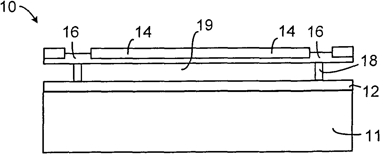
Problems solved by technology

Therefore, the transmitting and receiving performance of the transducer is poor
[0008] 2) Membrane support structures occupy useful areas of the transducer surface that do not contribute to transducer performance, reducing transducer efficiency
[0009] 3) There is a parasitic capacitance in the film support structure, which reduces the sensitivity of the transducer
[0010] 4) The periodic film support structure can also interfere with the normal operation of the transducer, thereby affecting the bandwidth of the transducer
[0011] 5) Due to the error of the manufacturing process, the mechanical properties of each unit in the transducer have certain differences
In addition, in Figure 1 The spring modulus and mass of the deformable thin-film capacitive micromachined ultrasonic transducer in
This affects the flexibility of the transducer design

Method used


Image

  • Micro-machined ultrasonic transducer
  • Micro-machined ultrasonic transducer
  • Micro-machined ultrasonic transducer

Examples


Embodiment 1

[0074] The capacitive micro-machined ultrasonic transducer is the most common micro-machined ultrasonic transducer, so the capacitive micro-machined ultrasonic transducer is taken as a specific example below for illustration.

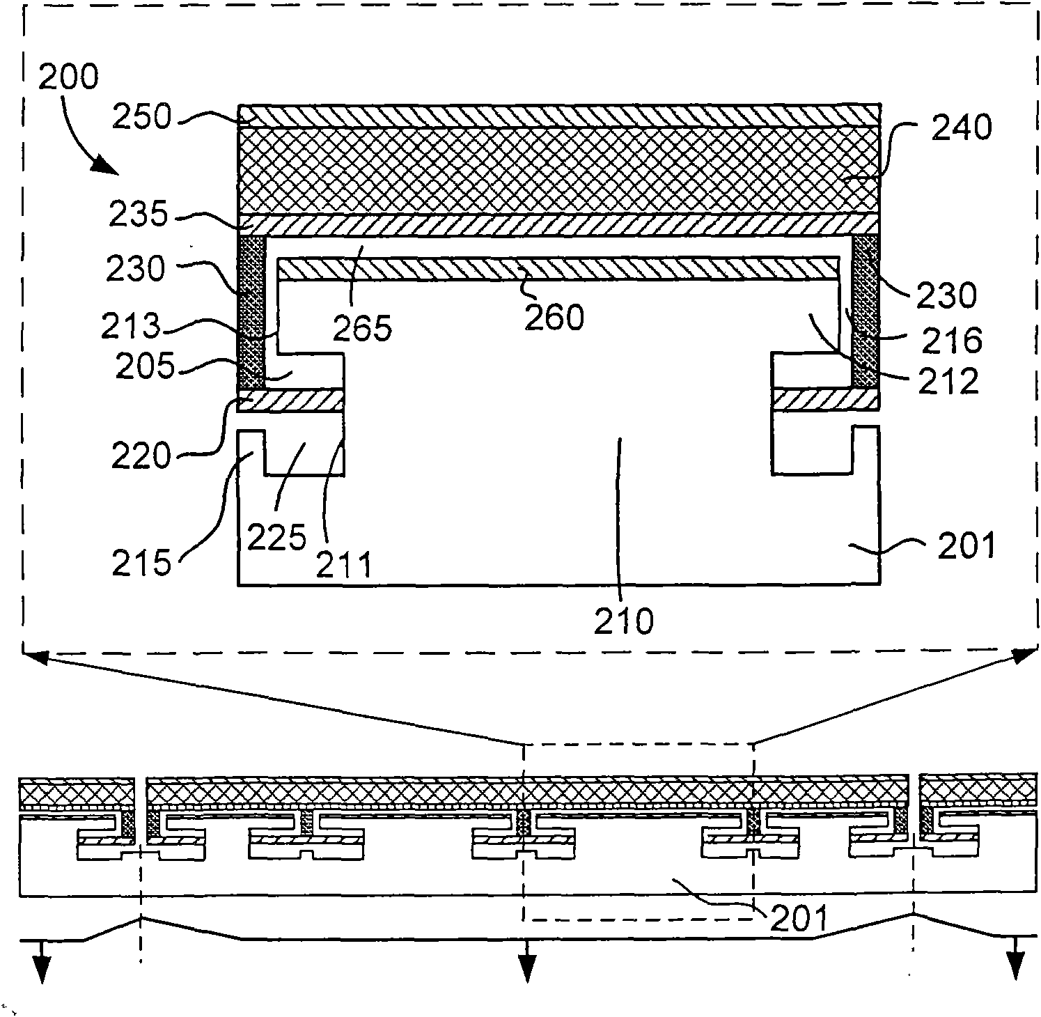
[0075] figure 2A schematic cross-sectional view of specific device embodiments (embodiments) of the spring-embedded capacitive micromachined ultrasonic transducer in the first invention is shown. In the dotted rectangular window is an enlarged view of a basic structural fragment 200 of a capacitive micromachined ultrasound transducer. The basic structural segment 200 of the micromachined ultrasound transducer is a part of a complete transducer or transducer array CMUT1. The transducer or transducer element CMUT1 can be a single device, or a part of a device with multiple elements (eg CMUT1, CMUT2 and CMUT3 as shown).

[0076] The basic structure segment 200 of the transducer is used to illustrate and understand the structure and working principle of ...

Embodiment 2

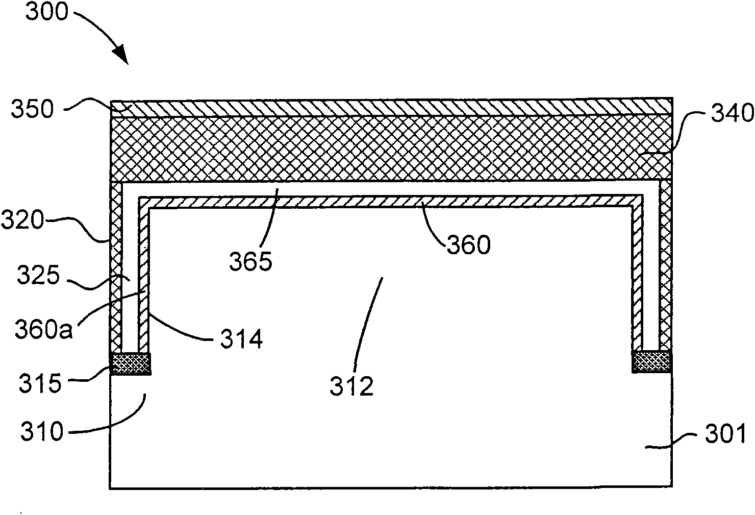
[0094] image 3 A cross-sectional schematic diagram showing the basic structural fragments of specific embodiments of the spring-embedded capacitive micromachined ultrasonic transducer in the second invention. is a spring-embedded capacitive micromachined ultrasonic transducer (the entire transducer is the same figure 2 same, but not in image 3 An enlarged view of the basic structural fragment 300 shown in ). The two spring-like structures shown in the figure are only for the convenience of structural description of the transducer, but according to design requirements, the basic structural segment 300 of the transducer may have different numbers of the same or different spring-like elastic structures.

[0095] The basic structural segment 300 of the spring-embedded capacitive micromachined ultrasonic transducer is made on a substrate 301 . Substrate 301 is a substrate that can be viewed as an upper portion 312 and a lower portion 310 . A surface sheet 340 overlies the uppe...

Embodiment 3

[0100] Figure 4 It shows a cross-sectional schematic diagram of the basic component structure of the specific device device of the spring-embedded capacitive micro-machined ultrasonic transducer in the third invention. Figure 4 is a spring-embedded capacitive micromachined ultrasonic transducer (the entire transducer is the same figure 2 same, but not in Figure 4 An enlarged view of the basic unit 400 shown in ). Two spring-like elastic mechanisms are shown in the figure for the convenience of structural description of the transducer, but according to design requirements, the basic structural segment 400 of the transducer may have different numbers of the same or different spring-like structures.

[0101] The basic structural segment 400 of the transducer is very similar to the basic structural segment 300 of the transducer. The basic structural segment 400 of the transducer has a spring like vertical elastic connector 420 which is curved and connects the surface sheet ...


PUM


Abstract

The invention relates to a micro-machined ultrasonic transducer and specifically relates to a spring embedded type micro-machined ultrasonic transducer, in particular to a spring embedded type capacitive micro-machined ultrasonic transducer. The micro-machined ultrasonic transducer comprises a first support layer and a second support layer, wherein a first electrode is arranged on the first support layer, a second electrode is arranged on the second support layer, the second support layer is a substrate, an open structure is arranged on the substrate, the substrate is divided into an upper part and a lower part, and the second electrode is arranged on the upper part; and the first support layer is a commercial veneer, the first support layer is connected with the second support layer through a vertical elastic connector, and a gap is formed between the first support layer and the second support layer. As the micro-machined ultrasonic transducer has better transmitting and receiving performances, the whole surface of the transducer can be a useful region, and the micro-machined ultrasonic transducer can further have a perfect fill factor. The micro-machined ultrasonic transducer can reduce the parasitic capacitance, improve the sensitivity, the breakdown voltage and the design flexibility of the transducer, and improve the reliability and the bandwidth.

Description

technical field [0001] The present invention relates to a micromachined ultrasonic transducer (Micromachined Ultrasonic Transducer, MUT), in particular to a spring embedded micromachined ultrasonic transducer (ESMUT), in particular to a spring embedded capacitive micromachined ultrasonic transducer (Capacitive Micromachined Ultrasonic Transducer Having Embedded Springs, ESCMUT). technical background [0002] Capacitive Micromachined Ultrasonic Transducer (CMUT) is an electrostatic transducer with a wide range of uses. Ultrasonic transducers can work in various media like liquids, solids and gases. Ultrasonic transducers have been used in medical diagnosis and treatment, non-destructive material testing, sonar, communication, proximity transducers, flow measurement, real-time process control, ultrasonic microscopy and other fields. [0003] Compared with widely used transducers made of piezoelectric ceramic (PZT) technology, capacitive micromachining ultrasonic transducers ...

Claims


Application Information

Patent Timeline
Patent Type & Authority Applications(China)
IPC IPC(8): B81B7/02B81C3/00B81C1/00B81B7/04
Inventor 漆斌庄雪锋
Owner KAILONGMED TECH CO LTD
Learn More