
Electromagnetic pump driving method

a technology of electromagnetic pump and electromagnetic field, which is applied in the direction of pump control, motor parameter, dynamo-electric machines, etc., can solve the problems of water hammer also producing vibration and noise, the timing of the valve closing from an opened state is slightly delayed, and the plunger movement speed is eased, and the cylinder side walls are sped up. , the effect of reducing the vibration of the cylinder side walls

Inactive Publication Date: 2007-02-01
SHINANO KENSHI
View PDF6 Cites 15 Cited by
  • Summary
  • Abstract
  • Description
  • Claims
  • Application Information

AI Technical Summary

Benefits of technology

[0012] By using the method of driving an electromagnetic pump described above, a pulse voltage is applied alternately on a positive side and a negative side to drive the electromagnetic coil such that a change in voltage that occurs when the polarity of the pulse voltage is inverted has a continuous slope at least between the positive side and the negative side, or the current flowing through the electromagnetic coil is detected and a supplying of current is controlled so that a pulse current flows where a change in current when the polarity of the current is inverted has a continuous slope at least between a positive side and a negative side, and therefore the excitation direction of the electromagnetic coil is not abruptly inverted. Accordingly, the movement speed of the plunger is eased and abrupt fluctuations in the pressure of the pump chamber are reduced, making it possible to reduce vibration in the cylinder side walls due to abrupt fluctuations in the force that acts on the inner surfaces of the pump chamber. It is also possible to reduce vibration in the stator due to abrupt fluctuations in the electromagnetic force that acts on the electromagnetic coil on the stator. In addition, reverse flow of the fluid when an intake valve or an outflow valve is closed is reduced, thereby easing the water hammer phenomenon and reducing the production of noise and vibration.
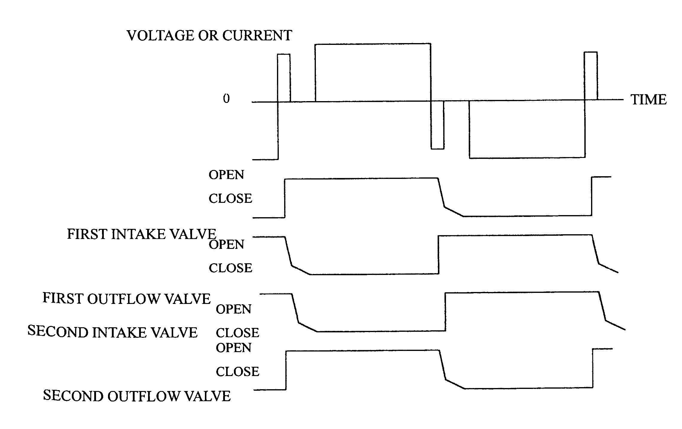
[0013] Also, by having a pulse voltage applied or a pulse current flow with a period where a value of the voltage or current is zero when the polarity of a driving voltage or a supplied current of the electromagnetic coil is inverted, it is possible to reduce the closing speed of the intake valve or outflow valve for fluid in the pump chamber, reducing reverse flow and easing the water hammer phenomenon, thereby reducing the production of noise and vibration.
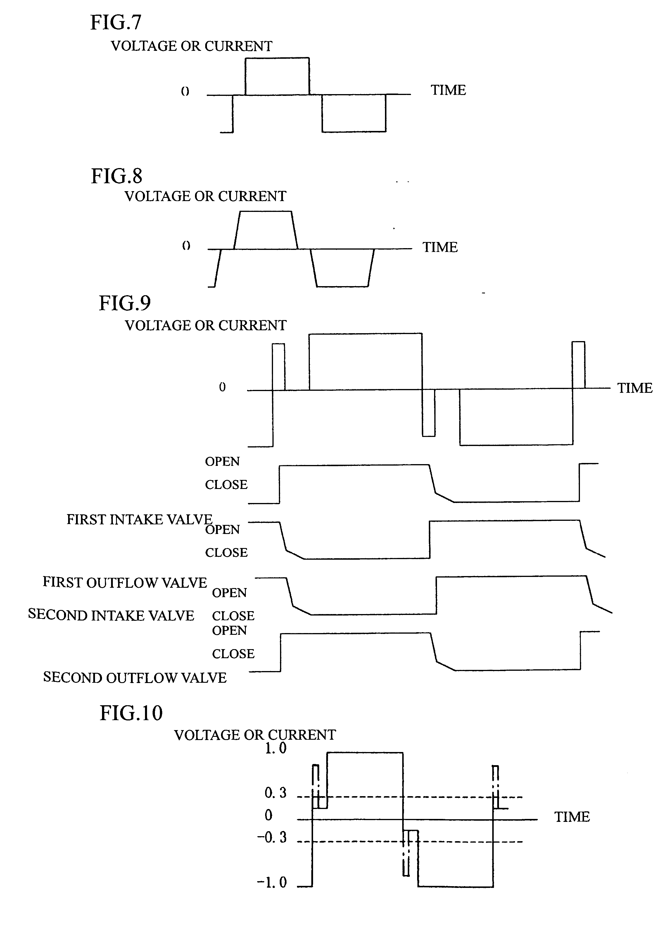
[0014] Also, by having a pulse voltage applied or a pulse current flow so that an offset voltage of no greater than 30% of a maximum voltage is applied or an offset current of no greater than 30% of a maximum current flows in advance when the polarity of a driving voltage or a supplied current of the electromagnetic coil is inverted, it is possible to reduce the closing speed of the intake valve or outflow valve for fluid on the pump chamber before the maximum voltage is applied or the maximum current flows with the inverted polarity, reducing reverse flow and easing the water hammer phenomenon and thereby reducing the production of noise and vibration. Biasing of the thrust that acts on the plunger in the non-excitation state can be eased by adjusting the offset voltage or offset current so that weak excitation is produced in the opposite direction to the direction of the thrust that acts on the plunger.
[0015] Also, by having a minute voltage pulse of at least 30% of a maximum voltage applied or a minute current pulse of at least 30% of a maximum current flow before the period where the value of the voltage or current is zero or the period where the offset voltage is applied or the offset current flows, it is possible to shorten the excitation period for weakening the previous excitation state of the electromagnetic coil, thereby reducing the drop in pump efficiency.

Problems solved by technology

In addition, when the first intake valve and the second outflow valve or the first outflow valve and the second intake valve are opened, noise and vibration are produced when the valves strongly collide with and come to rest upon engaging surfaces of the frames that form the pump chambers.
In addition, although the first intake / outflow valves and the second intake / outflow valves are opened and closed due to changes in pressure inside the pump chamber that accompany movement of the plunger, for any of the valves, compared to when the valve is opened from a closed state, the timing at which the valve is closed from an opened state is slightly delayed due to the fluid temporarily flowing in the opposite direction to the preceding direction of flow.
This water hammer also produces vibration and noise.

Method used


Image

  • Electromagnetic pump driving method
  • Electromagnetic pump driving method
  • Electromagnetic pump driving method

Examples


first embodiment

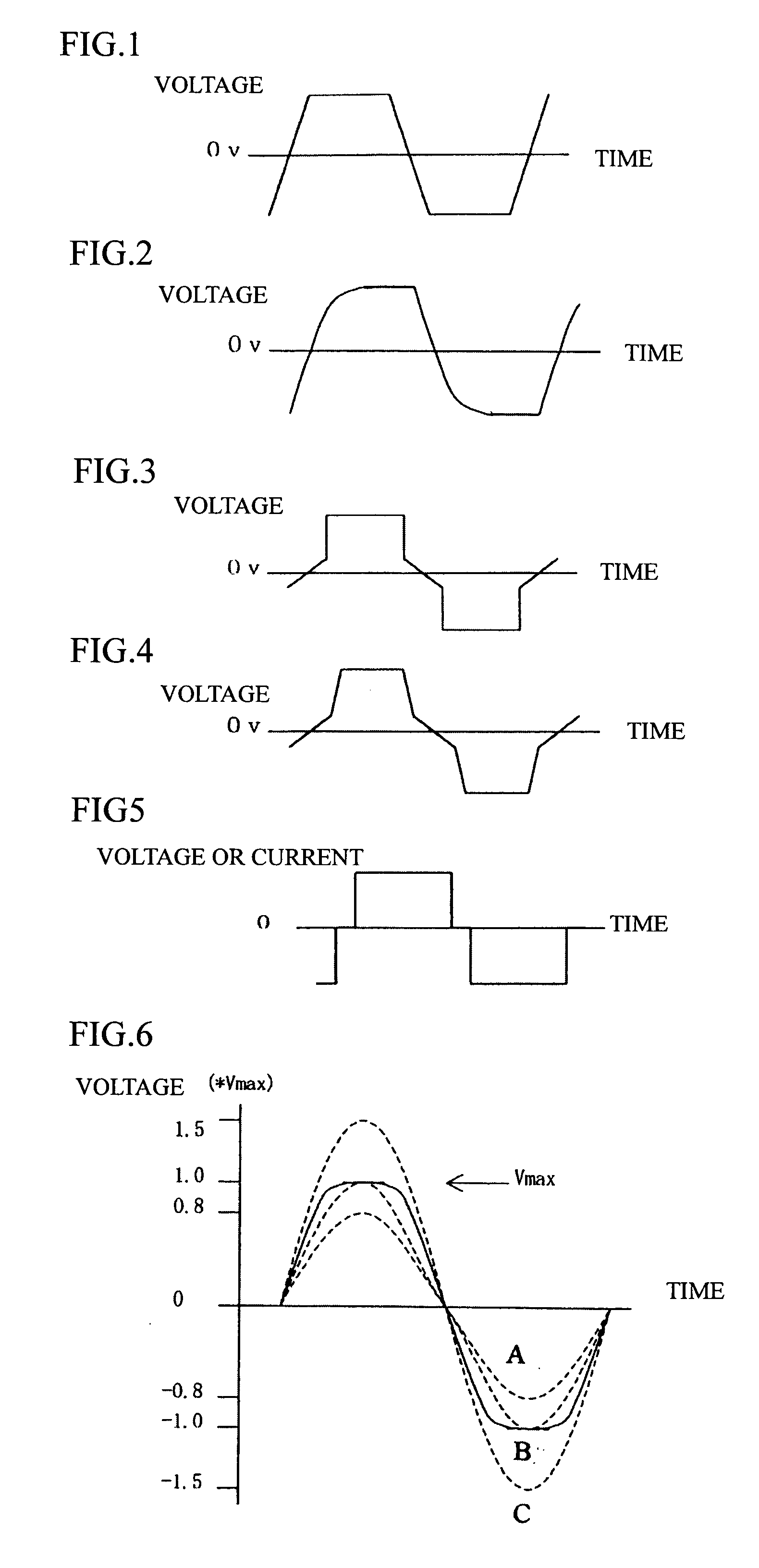
[0046] Next, to overcome the problems that accompany the opening and closing of the valves described above, preferred embodiments of a method of driving an electromagnetic pump will be described with reference to FIGS. 1 to 4. FIGS. 1 to 4 show voltage waveforms applied to both ends of the electromagnetic coils 50a, 50b. It should be noted that the driving voltage (pulse voltage) supplied to the electromagnetic coils 50a, 50b is generated by a driving control circuit, not shown, and as examples, a DC pulse voltage may be generated from a DC power supply voltage or a DC pulse voltage may be generated by rectifying an AC power supply voltage.

[0047]FIG. 1 shows the case where a pulse voltage is applied alternately on a positive side and a negative side to drive the electromagnetic coils 50a, 50b such that a change in voltage that occurs when the polarity of the pulse voltage is inverted has a continuous linear slope at least between the positive side and the negative side. FIG. 2 show...

second embodiment

[0049] Next, another example of a method of driving an electromagnetic pump will be described with reference to FIGS. 5 and 6. FIGS. 5 and 6 show_voltage waveforms applied to both ends of the electromagnetic coils 50a, 50b or current waveforms that flow in the electromagnetic coils 50a, 50b. FIG. 5 shows the case where a sinewave-shaped pulse voltage is applied to drive the electromagnetic coils 50a, 50b. By applying the sinewave-shaped pulse voltage, the change in voltage is made more gentle when the polarity is inversed, so that the speed of movement of the plunger 10 is eased and abrupt fluctuations in the pressure inside the pump chambers 30a, 30b can be reduced. By doing so, vibration of the cylinder wall surfaces due to abrupt changes in the forces that act on the inner surfaces of the pump chambers can be reduced, and vibration of the stator due to the abrupt fluctuations in the electromagnetic force that acts on the electromagnetic coils 50a, 50b of the stator can be reduced...

third embodiment

[0055] Next, another example of a method of driving an electromagnetic pump will be described with reference to FIGS. 7 to 9. FIGS. 7 to 9 show_voltage waveforms applied to both ends of the electromagnetic coils 50a, 50b or current waveforms that flow in the electromagnetic coils 50a, 50b.

[0056]FIGS. 7 and 8 show the case where a pulse voltage is applied or a pulse current flows so that there is a period where the voltage or current value is zero when the polarity of the driving voltage or the supplied current of the electromagnetic coils 50a, 50b is inverted. FIG. 8 shows the case where current or voltage changes with a linear slope before and after the zero voltage or zero current. By doing so, it is possible to reduce the speed of the valves opening and closing, to reduce the reverse flow, and to ease the water hammer phenomenon, and thereby to reduce the production noise and vibration. As one example, the noise level is 23 dB when the method of driving shown in FIG. 7 is used, ...


PUM


Abstract

There is provided a method of driving an electromagnetic pump where noise and vibration that accompany abrupt fluctuations in pressure inside a pump chamber are reduced. A pulse voltage is applied alternately on a positive side and a negative side to drive the electromagnetic coil such that a change in voltage that occurs when the polarity of the pulse voltage is inverted has a continuous slope at least between the positive side and the negative side.

Description

TECHNICAL FIELD [0001] The present invention relates to a method of driving an electromagnetic pump, and in more detail to a method of driving an electromagnetic pump used to convey a fluid such as a gas or a liquid. BACKGROUND ART [0002] The present applicant has previously proposed a smaller and slimmer electromagnetic pump where a plunger composed of a magnetic material is housed inside a cylinder of a stator so as to be capable of reciprocal movement and a current is passed through a single-phase electromagnetic coil fitted around the cylinder so that in one pump chamber out of the pump chambers formed between both end surfaces of the cylinder and both side surfaces in the direction of movement of the plunger, fluid is introduced from outside via a first valve and fluid is expelled to the outside via a second valve, with the same pumping action being realized in the other pump chamber. By passing a current through the electromagnetic coil, the plunger is caused to move in the ax...

Claims


Application Information

Patent Timeline
Patent Type & Authority Applications(United States)
IPC IPC(8): F04B49/06F04B17/04H02K33/16H02P25/06
CPCF04B17/04F04B2203/0402F04B49/065
Inventor YAGUCHI, FUMIHIROTASHIMA, MASAHARU
Owner SHINANO KENSHI
Learn More