
Assembly for collecting samples for purposes of identification or analysis and method of use

a technology for collecting samples and identifying or analysing samples, which is applied in the field of collecting samples, can solve the problems that the signal generated by the signal-generating means of the diagnostic equipment from the sample might not be strong enough to accurately identify or characterize the material, and the signal-generating means of the equipment are degraded, so as to achieve the effect of increasing the duration of the sample signal

Inactive Publication Date: 2007-02-01
UT BATTELLE LLC
View PDF16 Cites 23 Cited by
  • Summary
  • Abstract
  • Description
  • Claims
  • Application Information

AI Technical Summary

Benefits of technology

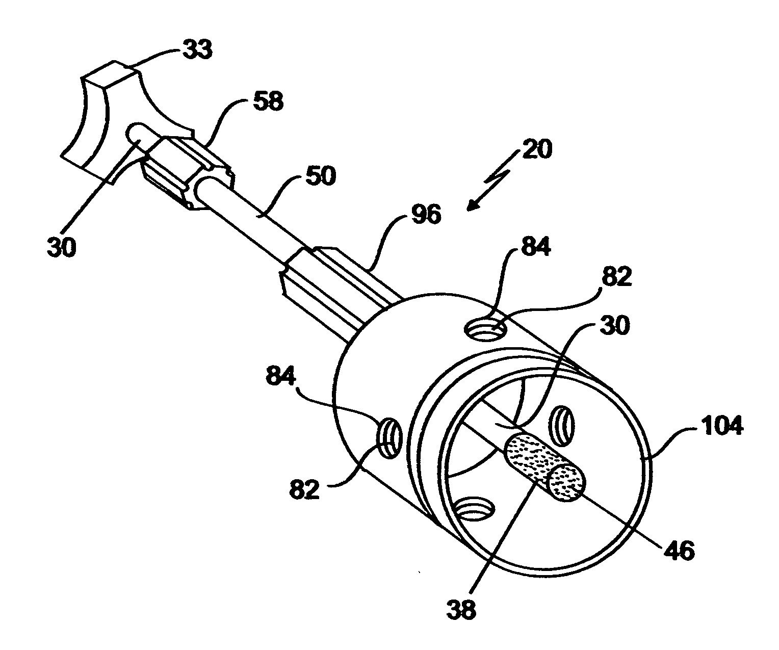
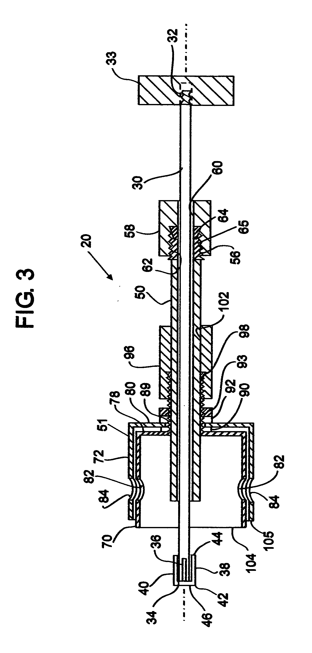
[0015] In one embodiment of the assembly, the assembly includes a cup section which is disposed about the elongated member so that the opening of the cup section is directed opposite the proximal end of the member and which is positionable about the collection tip of the assembly when the tip is placed adjacent the probe for transfer of an amount of the collected sample to the diagnostic equipment. By enclosing the airspace surrounding the collected sample as the sample is exposed to the probe, the cup section helps to focus, or direct, the collected sample upon the probe so that neither too much nor too little sample is ultimately transferred from the collection tip to the diagnostic equipment. Further still, the cup section increases the duration of the sample signal capable of being generated by the diagnostic equipment thereby allowing a fuller characterization of the sample by the diagnostic equipment.

Problems solved by technology

Such a prior art technique of transferring an amount of material from a source to the diagnostic equipment is limited in that volatile compounds (which may comprise the material to be analyzed) can dissipate very quickly from the wheel surface so that very little sample is ultimately transferred from the wheel surface to the diagnostic equipment (e.g. a mass spectrometer); and if the amount of sample which is conducted from the wheel surface to the diagnostic equipment is too small, then the signal which is generated by a signal-generating means of the diagnostic equipment from the sample might not be strong enough to accurately identify or characterize the material.
By comparison and in the case of materials which are comprised of less volatile compounds, too much material could be transferred from the wheel surface to the diagnostic equipment and ultimately degrade the signal-generating means of the equipment.

Method used


Image

  • Assembly for collecting samples for purposes of identification or analysis and method of use
  • Assembly for collecting samples for purposes of identification or analysis and method of use
  • Assembly for collecting samples for purposes of identification or analysis and method of use

Examples


Embodiment Construction

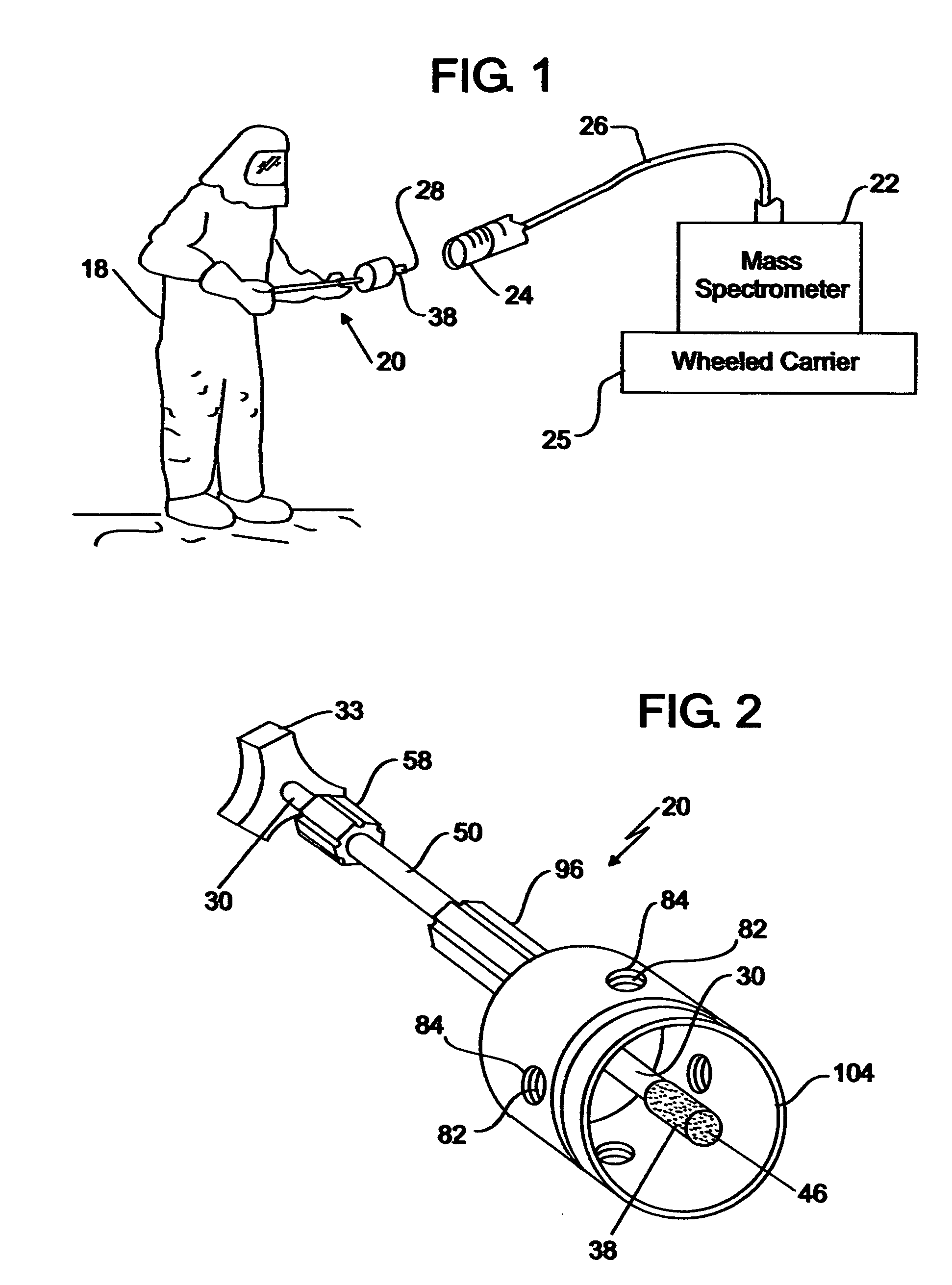
[0025] Turning now to the drawings in greater detail and considering first FIG. 1, there is illustrated an embodiment, generally indicated 20, of a collection assembly shown utilized with diagnostic equipment in an exemplary environment of intended use. In particular, the diagnostic equipment of the FIG. 1 environment includes a mass spectrometer 22 with which a sample 28 of material is to be identified or analyzed, a probe 24 which is associated with the mass spectrometer 22 and through which an amount of the sample 28 is introduced to the mass spectrometer 22, and a capillary tube 26 which is joined to so as to extend between the probe 24 and the mass spectrometer 22. During use of the FIG. 1 equipment, a sample of material desired to be identified or analyzed is placed adjacent the probe 24, and a pump (not shown) mounted internally of the mass spectrometer 22 draws an amount of the sample 28 (in a vaporized state) in sequence through the probe 24 and then through the capillary t...


PUM


Abstract

An assembly and an associated method for collecting a sample of material desired to be characterized with diagnostic equipment includes or utilizes an elongated member having a proximal end with which the assembly is manipulated by a user and a distal end. In addition, a collection tip which is capable of being placed into contact with the material to be characterized is supported upon the distal end. The collection tip includes a body of chemically-inert porous material for binding a sample of material when the tip is placed into contact with the material and thereby holds the sample of material for subsequent introduction to the diagnostic equipment.

Description

[0001] This invention was made with Government support under Contract No. DE-AC05-00OR22725 awarded by the U.S. Department of Energy to UT-Battelle, LLC, and the Government has certain rights to the invention.BACKGROUND OF THE INVENTION [0002] This invention relates generally to the obtaining of samples for purposes of identification or analysis and relates, more particularly, to a means for collecting such a sample from a source. [0003] The class of equipment with which this invention is utilized includes diagnostic equipment, such as a mass spectrometer, used for characterizing (e.g. identifying or analyzing) materials. It is not uncommon, for example, that military or rescue personnel occasionally come across material, such as a liquid contained in an unlabeled drum, that cannot be readily identified. Due to the chances that such material may be harmful or toxic to humans, it is important that the material be correctly identified or characterized before it is handled. For purpose...

Claims


Application Information

Patent Timeline
IPC IPC(8): B01L3/00
CPCG01N1/2214G01N35/1095Y10T436/2575G01N2001/028G01N2001/027
Inventor THOMPSON, CYRIL V.SMITH, ROB R.
Owner UT BATTELLE LLC
Learn More