Spectrum analyzer and method for correcting frequency errors

a spectrum analyzer and frequency error technology, applied in the field of spectrum analyzer and frequency error correction method, can solve the problems of inability to accurately correct errors in frequency sensitive applications, crystal oscillators often exhibit thermal variation in oscillation frequency, and significant degradation of spectrum analyzer performan

Active Publication Date: 2007-02-01
KEYSIGHT TECH
View PDF9 Cites 21 Cited by
  • Summary
  • Abstract
  • Description
  • Claims
  • Application Information

AI Technical Summary

Benefits of technology

[0008] In a further embodiment, the timing control signal includes timing signals separated by known time intervals and the error detection circuit includes a counter circuit for counting cycles of the reference signal occurring between successive timing signals to produce a count value indicative of the reference frequency. The error detection circuit further includes a processor for determining the reference frequency from the count value, determining the error in the reference frequency as a difference between the reference frequency and a desired frequency and producing the error correction signal to compensate for the error in the reference frequ

Problems solved by technology

As such, the performance of spectrum analyzers may be significantly degraded by frequency errors in the reference oscillator.
However, crystal oscillators often exhibit thermal variation in the oscillation frequency.
Although this frequency error is small in comparison to the nominal operating frequency, the error may be unacceptable in frequency sensitive applications.
For example, when measuring narrowband signals using local oscillators whose frequencies are derived from the reference oscillator, a 1 kHz frequency error in the reference oscillator can significantly reduce

Method used


Image

  • Spectrum analyzer and method for correcting frequency errors
  • Spectrum analyzer and method for correcting frequency errors
  • Spectrum analyzer and method for correcting frequency errors

Examples


Embodiment Construction

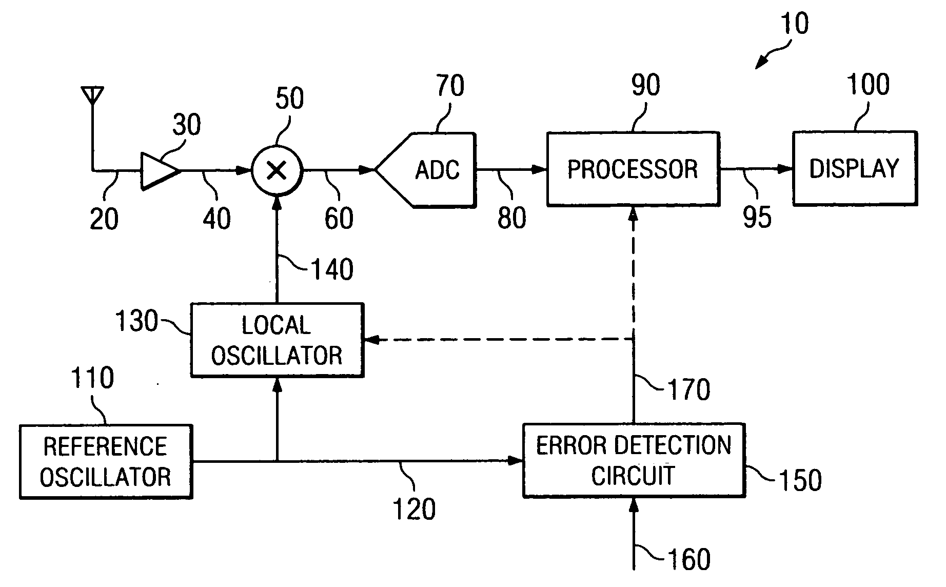
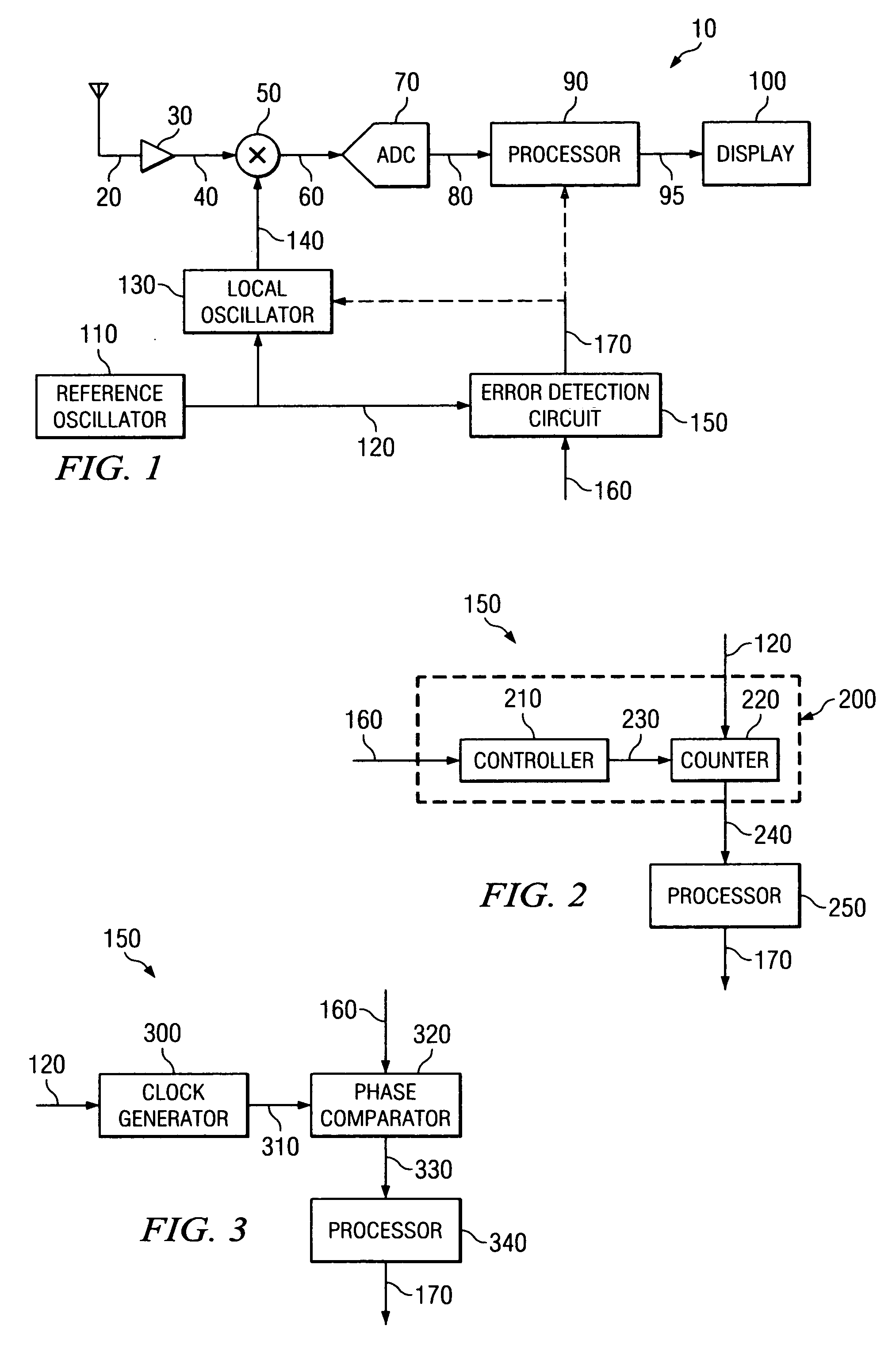
[0018]FIG. 1 is a schematic block diagram illustrating an exemplary and simplified spectrum analyzer 10, in accordance with embodiments of the present invention. For example, the spectrum analyzer 10 shown in FIG. 1 can represent exemplary components of an AGILENT TECHNOLOGIES, INC. model E4440 PSA series Spectrum Analyzer.

[0019] The spectrum analyzer 10 includes a low noise amplifier (LNA) 30, mixer 50, one or more local oscillators 130 (only one of which is shown for convenience), analog-to-digital converter 70, processor 90 and display 100. In operation, the LNA 30 amplifies an inbound RF signal 20 to produce an amplified inbound RF signal 30. The LNA 30 provides the amplified inbound RF signal 40 to the mixer 50, which directly converts the amplified inbound RF signal 40 into an inbound low IF signal 60 based on a local oscillation signal 140 provided by the local oscillator 130. The local oscillation signal 140 establishes the center frequency CF for the measurements performed...


PUM


Abstract

A spectrum analyzer corrects for internal frequency errors in a reference oscillator using a timing control signal. The reference oscillator provides a reference signal at a reference frequency. An error detection circuit determines an error in the reference frequency using the timing control signal and produces an error correction signal for use by a frequency conversion device in adjusting an output frequency thereof to compensate for the frequency error in the reference frequency.

Description

BACKGROUND OF THE INVENTION [0001] Spectrum analyzers commonly contain a master or reference oscillator that generates a precise oscillation frequency to control the timing and measurement frequency of the analyzer. As such, the performance of spectrum analyzers may be significantly degraded by frequency errors in the reference oscillator. Typically, the reference oscillator is a crystal oscillator that provides a relatively stable oscillation frequency. However, crystal oscillators often exhibit thermal variation in the oscillation frequency. As a result, the oscillation frequency of a crystal oscillator may vary with ambient temperature. The amount of thermal instability is typically measured in parts per million and is used to specify the frequency precision of the crystal oscillator. From the frequency precision, the frequency error expected from the crystal oscillator can be determined. [0002] As an example, a crystal oscillator with a nominal operating frequency of 10 MHz with...

Claims


Application Information

Patent Timeline
IPC IPC(8): H04B7/00
CPCH03J7/065G01R23/173G01R23/16
Inventor GUILFORD, JOHN H.
Owner KEYSIGHT TECH
Why Eureka
Try Eureka