
Analyte sensor

a technology of analyte sensor and sensor body, which is applied in the field of analyte sensor, can solve the problems that current used devices are unable to provide data safely and reliably for certain periods of time, and achieve the effects of increasing the volume of fluid surrounding, increasing the diffusion rate, and increasing the volume of fluid

Active Publication Date: 2007-02-01
DEXCOM
View PDF118 Cites 402 Cited by
  • Summary
  • Abstract
  • Description
  • Claims
  • Application Information

AI Technical Summary

Benefits of technology

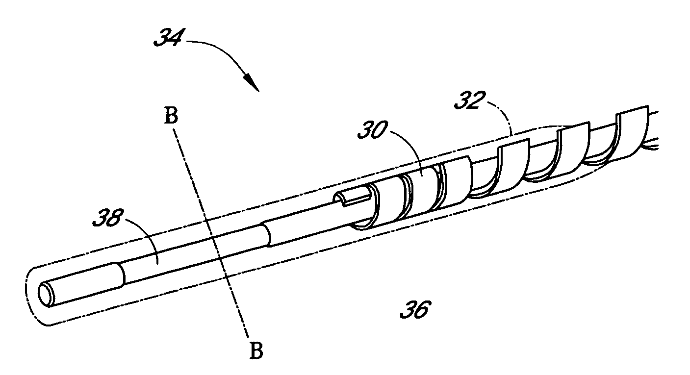
The patent describes an analyte sensing device that can be implanted into a host's tissue to measure the levels of a specific substance in the host. The device includes a sensor that is designed to increase the fluid bulk surrounding the sensor in the host, increase the diffusion rates of the sensor, and increase the function of the sensor in promoting fluid flow. The device can be made from a variety of materials, such as polymers, hydrogels, and biodegradable polymers. The device can also include a bioactive agent, such as an anti-inflammatory agent or an anti-infective agent, to help regulate the host's response to the implant. Overall, the device helps to create a fluid pocket around the sensor and promotes the growth of a tissue capsule around the sensor, which can help to protect the sensor and improve its function in the host.

Problems solved by technology

Despite the increasing number of individuals diagnosed with diabetes and recent advances in the field of implantable glucose monitoring devices, currently used devices are unable to provide data safely and reliably for certain periods of time.

Method used


Image

  • Analyte sensor
  • Analyte sensor
  • Analyte sensor

Examples


Embodiment Construction

[0105] The following description and examples illustrate a preferred embodiment of the present invention in detail. Those of skill in the art will recognize that there are numerous variations and modifications of this invention that are encompassed by its scope. Accordingly, the description of a preferred embodiment should not be deemed to limit the scope of the present invention.

DEFINITIONS

[0106] In order to facilitate an understanding of the preferred embodiment, a number of terms are defined below.

[0107] The term “biointerface” as used herein is a broad term, and is to be given its ordinary and customary meaning to a person of ordinary skill in the art (and is not to be limited to a special or customized meaning), and refers without limitation to any structure or substance that interfaces between host (tissue or body fluid) and an implantable device.

[0108] The term “biointerface membrane” as used herein is a broad term, and is to be given its ordinary and customary meaning to...


PUM


Abstract

Biointerface membranes are provided which can be utilized with implantable devices, such as devices for the detection of analyte concentrations in a biological sample. More particularly, methods for monitoring glucose levels in a biological fluid sample using an implantable analyte detection device incorporating such membranes are provided.

Description

RELATED APPLICATIONS [0001] This application is a continuation-in-part of U.S. application Ser. No. 11 / 439,630, filed May 23, 2006, which is a continuation-in-part of U.S. application Ser. No. 11 / 077,715, filed Mar. 10, 2005, which claims the benefit of U.S. Provisional Application No. 60 / 587,787 filed Jul. 13, 2004; U.S. Provisional Application No. 60 / 587,800 filed Jul. 13, 2004; U.S. Provisional Application No. 60 / 614,683 filed Sep. 30, 2004; and U.S. Provisional Application No. 60 / 614,764 filed Sep. 30, 2004. U.S. application Ser. No. 11 / 439,630 claims the benefit of U.S. Provisional Application No. 60 / 683,923 filed May 23, 2005. Each of the aforementioned applications is incorporated by reference herein in its entirety, and each is hereby expressly made a part of this specification.FIELD OF THE INVENTION [0002] Biointerface membranes are provided which can be utilized with implantable devices, such as devices for the detection of analyte concentrations in a biological sample. Mo...

Claims


Application Information

Patent Timeline
Patent Type & Authority Applications(United States)
IPC IPC(8): A61B5/00
CPCA61B5/14532A61B5/14865A61B5/411A61B5/418G01N33/66A61B2562/08C12Q1/006G01N33/54366A61B5/6848A61B5/1473Y02A50/30
Inventor BRAUKER, JAMES H.BOOCK, ROBERTRIXMAN, MONICASIMPSON, PETER C.BRISTER, MARK
Owner DEXCOM
Learn More