Sensor configuration

a biosensor and configuration technology, applied in the field of sensor configuration, can solve the problems of serious skin damage, limited use, and limited use of biosensors of this type, and achieve the effect of reducing the risk of environmental “noise interference”

Inactive Publication Date: 2007-02-01
TOUMAZ TECH
View PDF19 Cites 113 Cited by
  • Summary
  • Abstract
  • Description
  • Claims
  • Application Information

AI Technical Summary

Benefits of technology

[0024] Embodiments of the present invention allow the properties of the wireless link to be configured according to the location of the user. As the user roams between regions having different regulatory requirements, the properties of the wireless link can be changed or adjusted accordingly. This ensures that the equipment meets the local regulatory requirements and, more importantly, reduces the risk that environmental “noise” will interfere with the wireless link.

Problems solved by technology

Biosensors of this type have their limitations.
In particular, due to the need for users to prick their skin to obtain a blood sample, and to then perform a short but still inconvenient test procedure using the biosensor, users may not perform the test as often as required.
Skin pricking is also painful and, over the long term, can result in serious skin damage.
These problems apply equally to other types of biosensors which measure analytes present in blood and thus require the provision of blood samples; for example the measurement of oxygen, lactate, nitric acid, creatinie, dopamine, serotonin, noradrenaline.

Method used


Image

  • Sensor configuration
  • Sensor configuration
  • Sensor configuration

Examples


Embodiment Construction

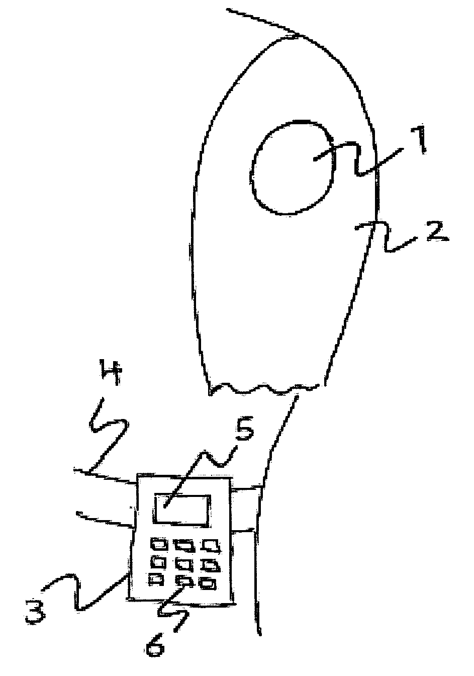
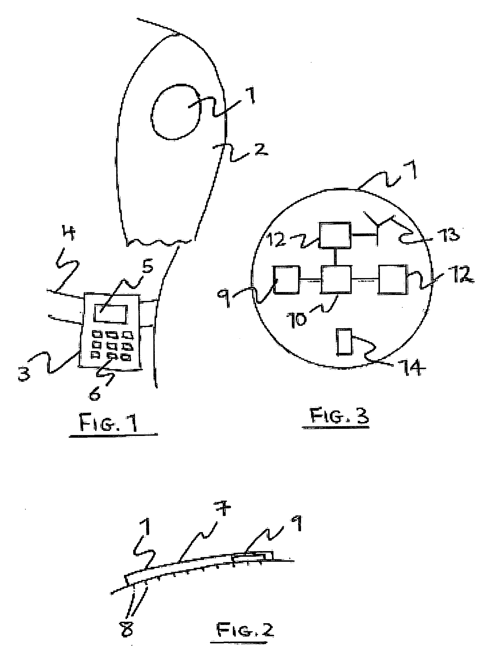
[0070] There is illustrated in FIG. 1 a human wearable monitoring system. This may be suitable, for example, for continuously monitoring the glucose level of a user suffering from diabetes. The system comprises two main components: a disposable sensor 1 in the form of a patch that is affixed to a user's skin, e.g. the arm 2, and a controller 3 which, in the example show, is attached to the user's belt 4. The controller 3 comprises a user interface including a liquid crystal display (LCD) 5 and a keypad 6.

[0071]FIG. 2 shows a cross-sectional view of the sensor patch 1, affixed to the user's skin. The patch 1 comprises a flexible carrier 7 which may be of a plastics or fabric material, or of a metal foil. The underside of the carrier may be coated with an adhesive to allow the patch to be fixed to the skin, if the carrier is itself not sufficiently “sticky”. Projecting from the underside of the patch is an array, e.g. 100, of micro-needles 8. These are typically 1-1000 micrometers in...


PUM


Abstract

Apparatus for monitoring and or treating a substance or body. The apparatus comprises a sensor 1, at least a portion of which 6 is arranged in use to come into contact with a body, tissue, bodily fluid or other substance, and a computer device 3. Both the sensor 1 and the computer device 3 have radio frequency circuitry 12,16 for facilitating the transmission of data between them via a wireless communication link, the computer device 3 having means 15,17 for selecting wireless link transmission properties based upon user location, and for signalling these properties to the sensor 1.

Description

FIELD OF THE INVENTION [0001] The present invention relates to the configuration of sensors and in particular, though not necessarily, to the configuration of body implantable and wearable medical biosensors. BACKGROUND TO THE INVENTION [0002] A “biosensor” has been defined as an analytical device incorporating a biological or biologically-derived sensing element either integrated within or intimately associated with a physicochemical transducer. Biosensors are generally designed to produce either discrete or continuous digital electronic signals that are proportional to a single analyte or a related group of analytes, although the provision of analogue signals should not be excluded. [0003] There are many areas of application for biosensors including for example environmental sensing, chemical production, and food and drink production and preparation. One area of application that has attracted a great deal of interest however is that of medical diagnostics, monitoring, and treatmen...

Claims


Application Information

Patent Timeline
Patent Type & Authority Applications(United States)
IPC IPC(8): A61N1/00A61B5/00
CPCA61B5/0002A61B5/1112A61B5/6824A61B5/6832A61B5/14532G01N27/416
Inventor BURDETT, ALISONPADDEN, PAUL
Owner TOUMAZ TECH
Why Eureka
Try Eureka