Thermal shield, especially for lining the wall of a combustion chamber

a technology of heat shield elements and combustion chambers, which is applied in the direction of machines/engines, lighting and heating apparatus, furnaces, etc., can solve the problems of limited service life achieve the effects of increasing the strength of heat shield elements, high tensile strength, and flexible shaping of heat shield elements

Inactive Publication Date: 2007-02-08
SIEMENS AG
View PDF14 Cites 14 Cited by
  • Summary
  • Abstract
  • Description
  • Claims
  • Application Information

AI Technical Summary

Benefits of technology

[0013] In this case, the invention is based on the idea that a heat shield element designed for especially long service life should be especially adapted to the external conditions of use. In order to make this possible and provide an especially high number of degrees of freedom for individual adaptation measures, the hitherto conventional production of heat shields by pressing is dispensed with and production by casting is now provided instead. However, in a cast ceramic heat shield, on account of only comparatively low tensile strength in particular in the longitudinal and transverse directions of the heat shield element, the service life of the heat shield element could be limited. In order to therefore enable a heat shield element based on a cast basic body to be used in a combustion chamber for utilizing the structural degrees of freedom achievable with said heat shield element, special measures with regard to the structural reinforcement of the basic body should be taken for long service life and increased passive safety, these measures also increasing the cohesion of the basic body in the event of possible crack formation.
[0027] The advantage of a casting operation consists in the possibility of producing more complex shapes of heat shield elements. Thus, on the one hand, the external basic shape can be varied comparatively easily and at a low cost. On the other hand, it is possible in a casting operation to integrally cast arrangements for fastening the heat shield elements to the combustion chamber wall. Thus, for example, grooves, holes, threads or also retaining devices can be integrally cast in cast heat shield elements.

Problems solved by technology

However, in a cast ceramic heat shield, on account of only comparatively low tensile strength in particular in the longitudinal and transverse directions of the heat shield element, the service life of the heat shield element could be limited.

Method used


Image

  • Thermal shield, especially for lining the wall of a combustion chamber
  • Thermal shield, especially for lining the wall of a combustion chamber
  • Thermal shield, especially for lining the wall of a combustion chamber

Examples


Embodiment Construction

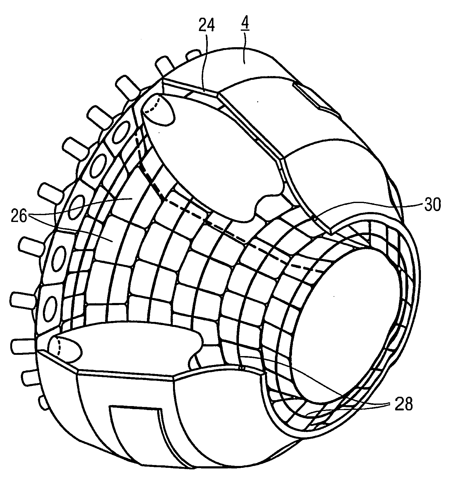
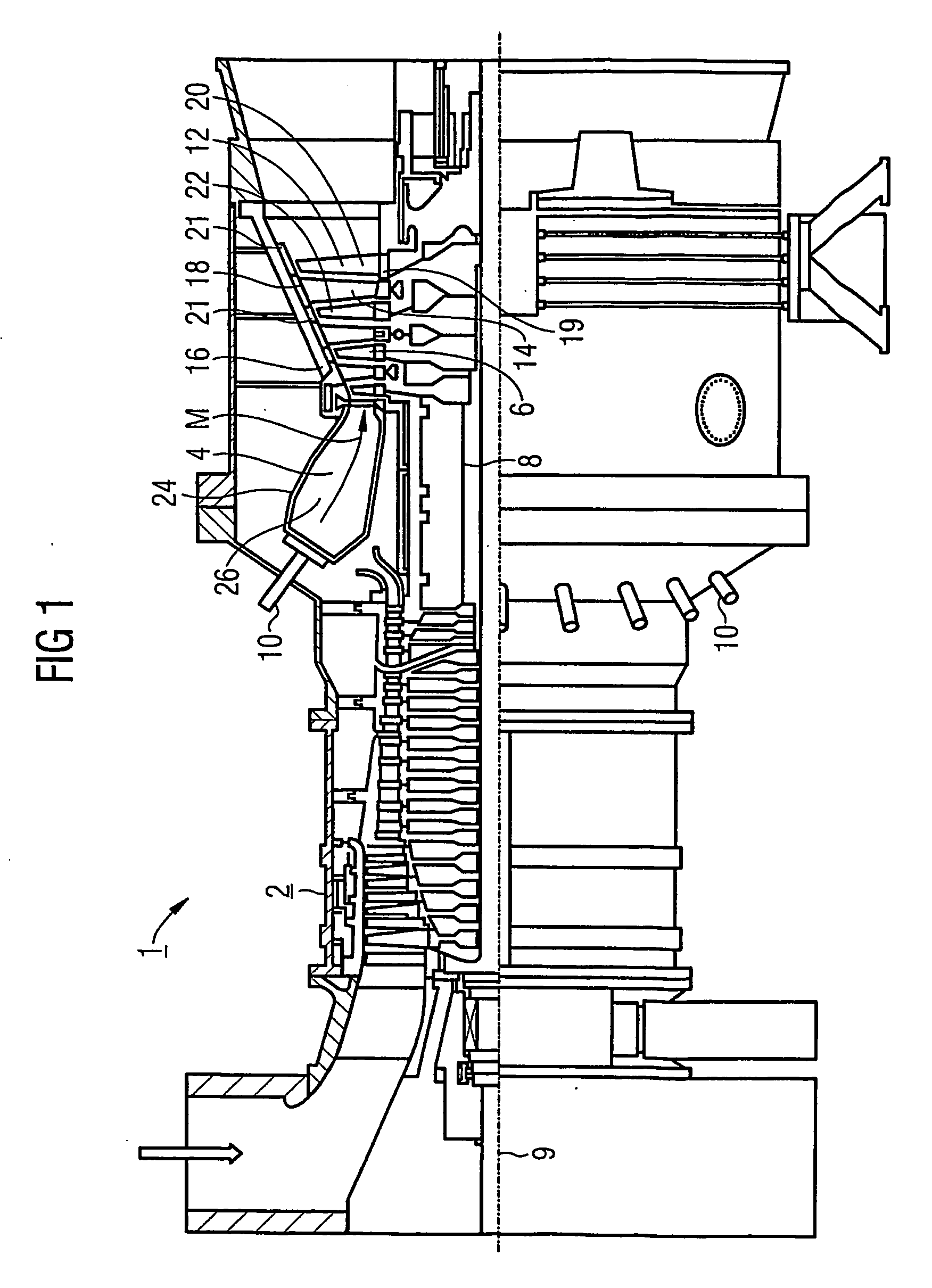
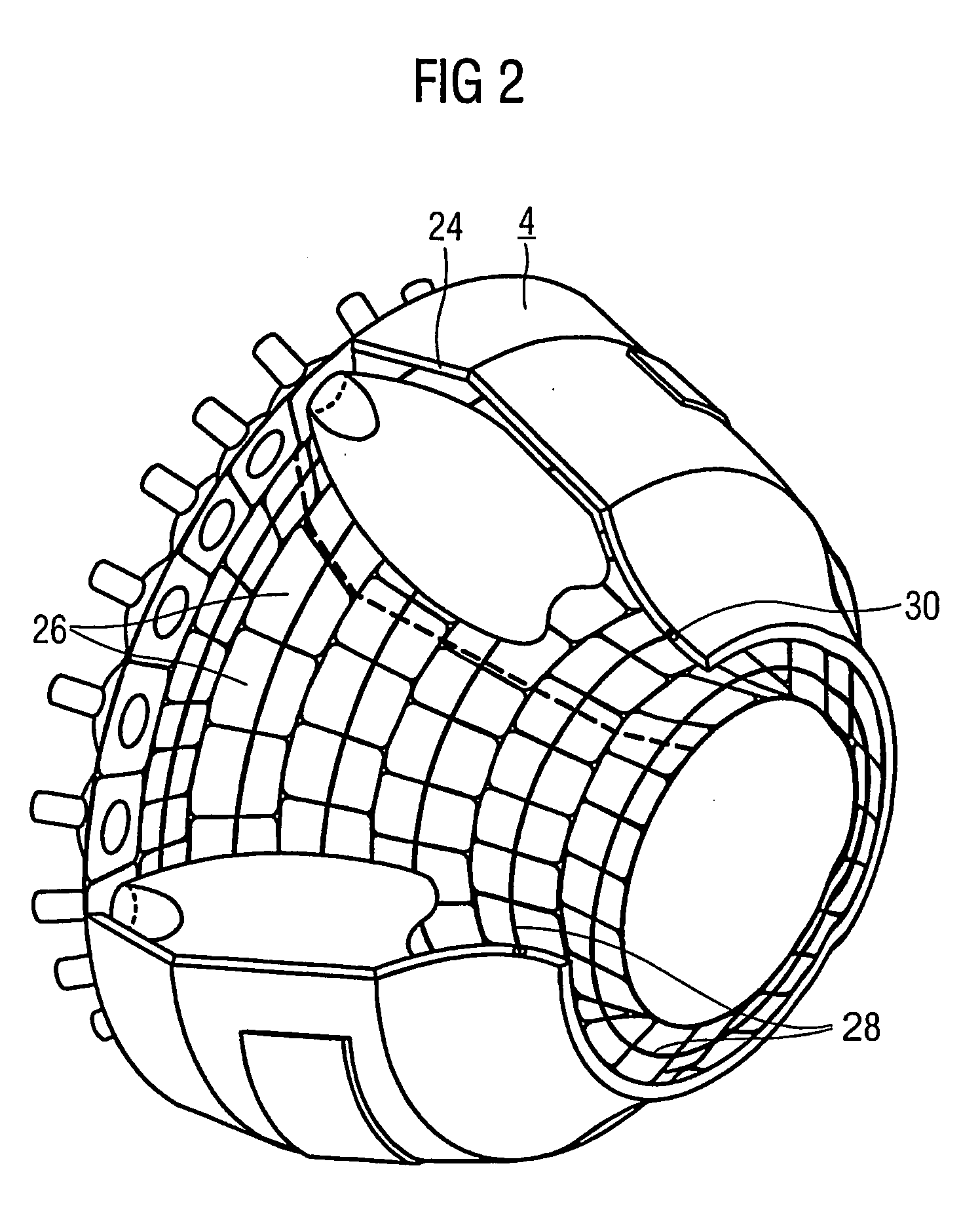
[0037] The gas turbine 1 according to FIG. 1 has a compressor 2 for combustion air, a combustion chamber 4 and a turbine 6 for driving the compressor 2 and a generator (not shown) or a driven machine. To this end, the turbine 6 and the compressor 2 are arranged on a common shaft 8, which is also referred to as turbine rotor and to which the generator or the driven machine is also connected and which is rotatably mounted about its center axis 9. The combustion chamber 4, designed like an annular combustion chamber, is fitted with a number of burners 10 for burning a liquid or gaseous fuel.

[0038] The turbine 6 has a number of rotatable moving blades 12 connected to the turbine shaft 8. The moving blades 12 are arranged in a ring shape on the turbine shaft 8 and thus form a number of moving blade rows. Furthermore, the turbine 6 comprises a number of fixed guide blades 14, which are likewise fastened in a ring shape to an inner casing 16 of the turbine 6 while forming guide blade rows...


PUM

PropertyMeasurementUnit
temperatureaaaaaaaaaa
tensile strengthaaaaaaaaaa
distanceaaaaaaaaaa

Abstract

The aim of the invention is to provide a highly durable, high-strength thermal shield element for the interior lining of the combustion chamber of a gas turbine. For this purpose, the thermal shield element comprises a base produced from a solidified cast ceramic material into which a plurality of reinforcing elements are integrated.

Description

CROSS REFERENCE TO RELATED APPLICATIONS [0001] This application is the US National Stage of International Application No. PCT / EP2004 / 012142, filed Oct. 27, 2004 and claims the benefit thereof. The International Application claims the benefits of European Patent application No. 03024560.9 filed Oct. 27, 2003. All of the applications are incorporated by reference herein in their entirety.FIELD OF THE INVENTION [0002] The invention relates to a heat shield element, in particular for the inner lining of a combustion chamber or a kiln. The invention also relates to a combustion chamber having an inner lining formed from heat shield elements and to a gas turbine having a combustion chamber. BACKGROUND OF THE INVENTION [0003] A combustion space subjected to high thermal and / or thermomechanical loading, such as, for example, a kiln, a hot-gas duct or a combustion chamber of a gas turbine, in which combustion space a hot medium is generated and / or directed, is provided with an appropriate li...

Claims


Application Information

Patent Timeline
Patent Type & Authority Applications(United States)
IPC IPC(8): F23R3/42C21B7/06F23R3/00F27D1/00F27D1/04F27D1/08F27D1/10
CPCC21B7/06F23R3/007F27D1/0033Y10T428/2949F27D1/08F27D1/10Y10T428/2973F27D1/04
Inventor GROTE, HOLGERKOLLENBERG, WOLFGANGTERTILT, MARC
Owner SIEMENS AG
Why Eureka
Try Eureka