Thermoelectric device and method of manufacturing the same

a technology of thermoelectric devices and manufacturing methods, applied in the direction of thermoelectric devices, thermoelectric device details, printed circuit aspects, etc., can solve the problems of insufficient supply, inability to obtain desired power generation performance, and deterioration of power generation efficiency, so as to improve the productivity and reliability of the device, improve the efficiency of the device, and simplify the structure

Inactive Publication Date: 2007-02-08
KK TOSHIBA
View PDF6 Cites 67 Cited by
  • Summary
  • Abstract
  • Description
  • Claims
  • Application Information

AI Technical Summary

Benefits of technology

[0021] According to the present invention, the thermoelectric device that is capable of improving a power generation performance while keeping a hermetic sealing after a heat cycle is applied, and also achieving simplification of a structure and improvement in productivity and reliability of a device by reducing the number of articles, and the method of manufacturing the same can be provided.

Problems solved by technology

This is because such a situation should be prevented that the thermoelectric element and the electrode are exposed to the high temperature and oxidized and then the power generation efficiency is deteriorated.
In this event, such disadvantages are caused that the heat absorbed from the high temperature side cannot be sufficiently supplied to the thermoelectric element, etc. and in some cases a desired power generation performance cannot be obtained.
However, in the invention disclosed in Patent Literature 1, such a case may be considered that improvement in the power generation performance of the thermoelectric device becomes difficult.
Therefore, an output density of the thermoelectric device cannot be enhanced and the power generation performance is lowered.
In particular, since a difference in coefficients of linear expansion between the ceramic substrate and the case is large, the load applied to the brazed portions is increased to generate the breakage, and an airtightness in the thermoelectric device is deteriorated to lower the power generation performance.
For example, when a thickness of the external electrode used to output an electromotive force from the thermoelectric device to the outside is thicker than that of the substrate and then a clearance is produced between the substrate of the thermoelectric device and the coolant, the thermal resistance between them is increased and a reduction in the power generation performance is caused.
Thus, a loss of heat transfer to the thermoelectric element is generated by an air layer existing in this clearance.
These losses of heat transfer result in a reduction in the power generation performance.

Method used


Image

  • Thermoelectric device and method of manufacturing the same
  • Thermoelectric device and method of manufacturing the same
  • Thermoelectric device and method of manufacturing the same

Examples


first embodiment

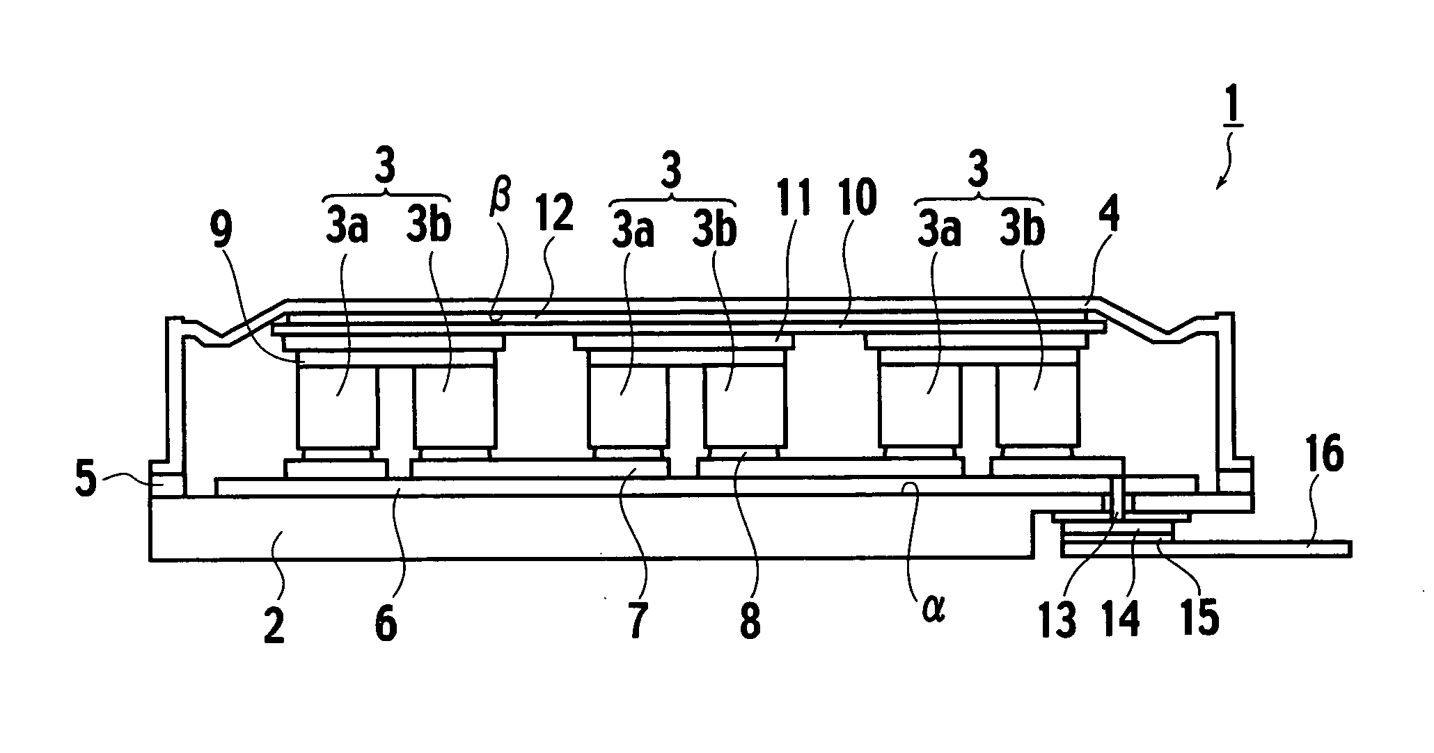
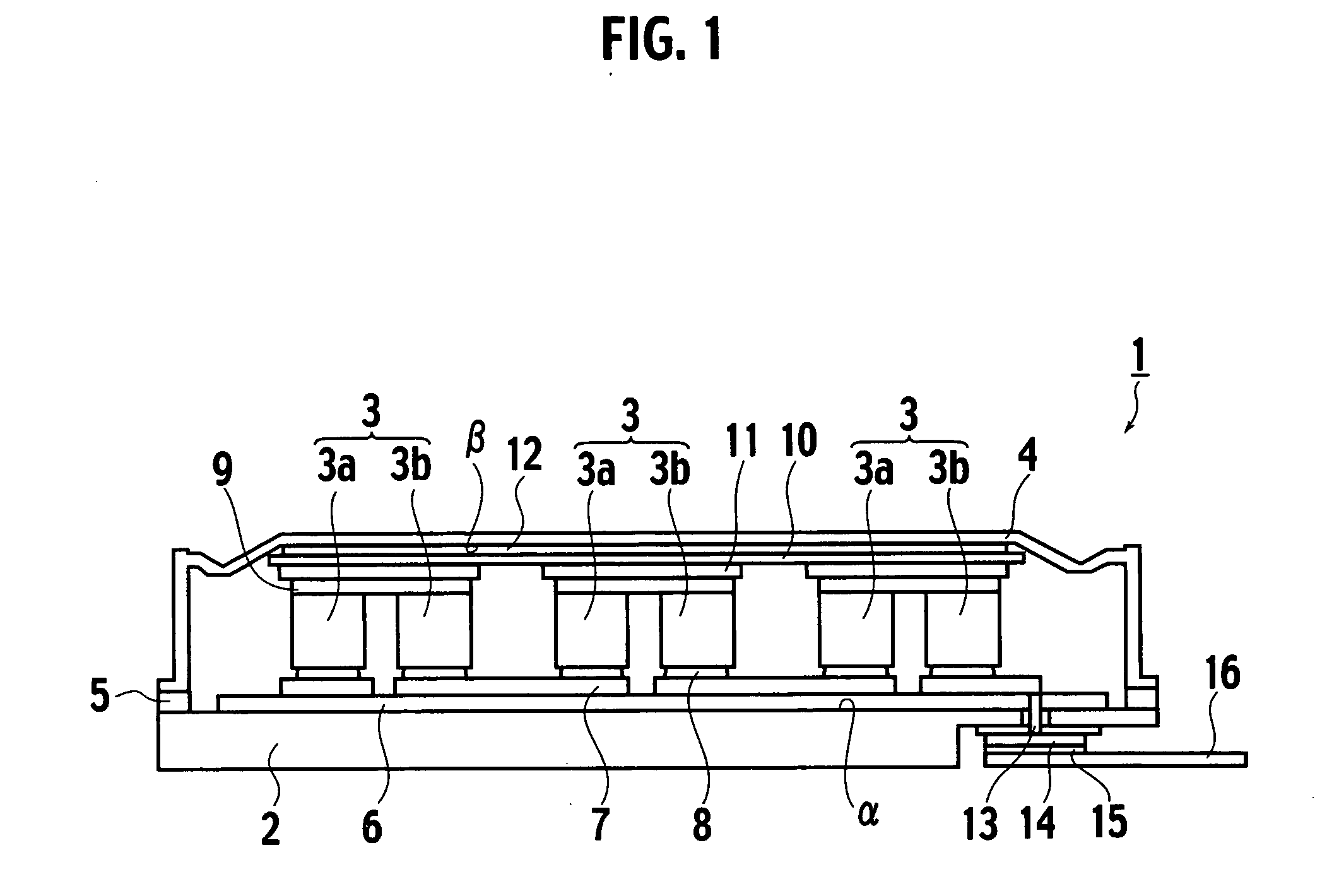
[0072] As shown in FIG. 1, a thermoelectric device (closed vessel) 1 according to a first embodiment of the present invention is constructed by a metal substrate 2 made of metal, thermoelectric elements 3 put on a center portion on a surface (referred appropriately to as a “first principal surface a” hereinafter) of the metal substrate 2, a lid 4 for covering upper surfaces and side surfaces of the thermoelectric elements 3, and a joining metal member 5 made of metal to hermetically seal the metal substrate 2 and the lid 4 in a peripheral portion of the first principal surface α. More particularly, all members constituting the vessel (thermoelectric device) 1, i.e., the metal substrate 2, the metal lid 4, and the joining metal member 5, are made of metal.

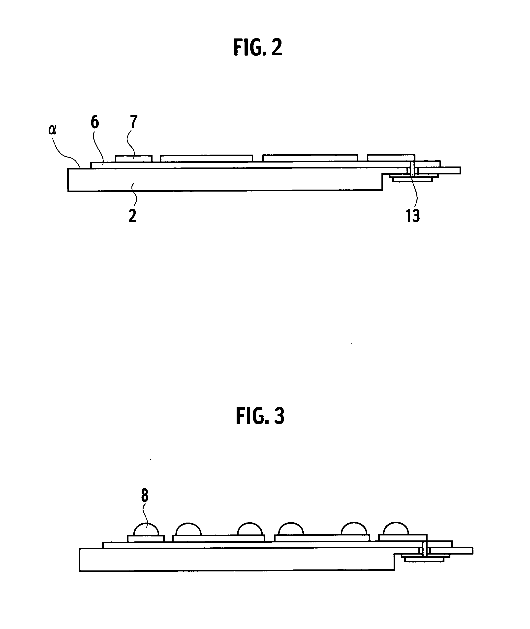
[0073] An insulating layer 6 is provided in the center portion on the first principal surface α, and first conductive wiring layers 7 are formed on the insulating layer 6. As the insulating layer 6, preferably a resin or a resin co...

second embodiment

[0125] Next, a second embodiment will be explained hereunder. In the second embodiment and respective variations of the second embodiment, the same reference symbols are affixed to the same constituent elements as those explained in the first embodiment, and thus their redundant explanations of the same constituent elements will be omitted herein.

[0126] As shown in FIG. 15, a thermoelectric device 31 according to the second embodiment of the present invention includes a substrate 32, the thermoelectric elements 3 on the substrate 32, and a lid 34, and also includes a spray deposit 35 formed to contact tightly an inner surface of the insulating lid 34.

[0127] The substrate 32 is constructed by an insulating substrate 32a, a metal film 32b provided on the insulating substrate 32a, and wiring layers 37. Here, the surface of the substrate 32 means the surface on which the thermoelectric elements are loaded, and the back surface of the same means the surface on which the metal film 32b ...

third embodiment

[0163] Next, a third embodiment will be explained hereunder. In the third embodiment, the same reference symbols are affixed to the same constituent elements as those explained in the first embodiment, and thus their redundant explanations of the same constituent elements will be omitted herein.

[0164]FIG. 26 is a sectional view of the thermoelectric device 1 according to the third embodiment. The electromotive force generated from the thermoelectric elements 3 is taken out to the outside of the thermoelectric device 1 to pass through the through hole wiring 13, the metal layer 14, the solder 15, and the external electrode 16 respectively. In the third embodiment, an insulating material 18 to insulate from the cooling medium is provided on the surface opposing to the surface that is connected to the solder 15 of the external electrode 16.

[0165] In the thermoelectric device 1, etc, in above respective embodiments, thicknesses of the metal substrate 2, and the like are reduced in the...


PUM

PropertyMeasurementUnit
temperatureaaaaaaaaaa
diameteraaaaaaaaaa
pressureaaaaaaaaaa

Abstract

There is provided a thermoelectric device capable of improving a power generation performance while keeping a hermetic sealing after a heat cycle is applied, and also achieving simplification of a structure and improvement in productivity and reliability of a device by reducing the number of articles, and a method of manufacturing the same.
A thermoelectric device, includes a metal substrate 2, a thermoelectric element 3 mounted on a center portion of a surface of the metal substrate 2, a metal lid 4 for covering an upper surface and side surfaces of the thermoelectric element 3, and a joining metal member 5 provided to a peripheral portion of a surface of the metal substrate 2 to hermetically seal a space between the metal substrate 2 and the lid 4.

Description

CROSS REFERENCE TO RELATED APPLICATION [0001] This application is based upon and claims the benefit of priority from the prior Japanese Patent Application No. 2005-224491, filed on Aug. 2, 2005, No. 2005-234133, filed on Aug. 12, 2005, No. 2005-239819, filed on Aug. 22, 2005, No. 2005-268516, filed on Sep. 15, 2005, No. 2006-198936, filed on Jul. 21, 2006, the entire content of which are incorporated herein by reference. BACKGROUND OF THE INVENTION [0002] 1. Field of the Invention [0003] The present invention relates to a thermoelectric device and a method of manufacturing the same and, more particularly, a thermoelectric device for converting heat into electricity or converting electricity into heat and a method of manufacturing the same. [0004] 2. Discussion of the Background [0005] The thermoelectric device is the device that utilizes the thermoelectric effect such as the Thomson effect, the Peltier effect, the Seebeck effect, or the like. As the devices that have already been ma...

Claims


Application Information

Patent Timeline
Patent Type & Authority Applications(United States)
IPC IPC(8): H01L35/00
CPCH01L35/10H01L35/32H05K1/0204H05K2201/10219H05K1/056H05K2201/066H05K1/0373H10N10/82H10N10/17
Inventor SOGOU, TAKAHIROTATEYAMA, KAZUKIHANADA, HIROYOSHISAITO, YASUHITOARAKAWA, MASAYUKIKONDO, NARUHITOTSUNEOKA, OSAMUIWANADE, NAOKAZU
Owner KK TOSHIBA
Why Eureka
Try Eureka