A separator element for a mesh cable duct and a mesh cable duct comprising such element

a technology of separator elements and mesh cables, which is applied in the direction of pipe supports, electrical appliances, pipes/joints/fittings, etc., can solve the problems of difficult to ensure the continuity of separator elements, upward or downward bends, etc., and achieves the effect of reducing the number of accessories, facilitating production and saving storage costs

Inactive Publication Date: 2007-02-08
LEGRAND ZIBIDO SAN GIACOMO
View PDF9 Cites 5 Cited by
  • Summary
  • Abstract
  • Description
  • Claims
  • Application Information

AI Technical Summary

Benefits of technology

[0017] Since, for mesh ducts, the bend accessories, whether they be flat bends, upward bends or downward bends, can easily be produced from straight duct modules (“duct module” meaning a minimum duct portion included between two transverse wires) by shearing of some of the wires and deformation of the remaining wire portions by bending, the separator element of the invention can be coupled—without modification—with any duct module, whether it forms part of a straight portion or of a bend accessory.
[0018] Advantageously, the provision of a single type of separator element, possibly reproduced in several height categories, drastically reduces the number of accessories for a series of cable-duct systems, and consequently storage costs.
[0019] The construction of the wire separator element also advantageously enables two or more longitudinal compartments to be demarcated within the cable-housing space without, however, leading to an actual physical and visual separation between them, thus enabling the cables which extend in the various compartments to be identified easily and quickly and permitting very easy output branching-off of the cables.
[0020] Finally, the separator element of the invention can be coupled firmly with the base of the duct simply by interference with portions of the longitudinal and transverse wires forming a mesh of the base of the duct, and hence without requiring the use of clamping accessories or operating tools, permitting quick and easy installation and configuration of a cable duct as well as setting-up of power and / or signal circuits.

Problems solved by technology

The greatest disadvantage of this solution is that it is difficult to ensure the continuity of the separator element also in the region of direction-changing accessories such as flat, upward or downward bends.

Method used


Image

  • A separator element for a mesh cable duct and a mesh cable duct comprising such element
  • A separator element for a mesh cable duct and a mesh cable duct comprising such element
  • A separator element for a mesh cable duct and a mesh cable duct comprising such element

Examples


Embodiment Construction

[0027] In the following description and claims, terms such as “longitudinal” and “transverse” as well as “vertical” and “horizontal” are intended to refer to the normal arrangement of a cable duct, to the orientations of the drawings and to the condition in which a separator element is fitted in a duct. In particular, “longitudinal direction” is defined as the main extension direction of the duct and hence of the cables therein, “longitudinal plane” defines a vertical plane identified by the longitudinal direction, “transverse direction” defines the direction perpendicular to a longitudinal plane, and “transverse plane” or “transverse cross-section” defines a section plane perpendicular to the longitudinal direction of the duct.

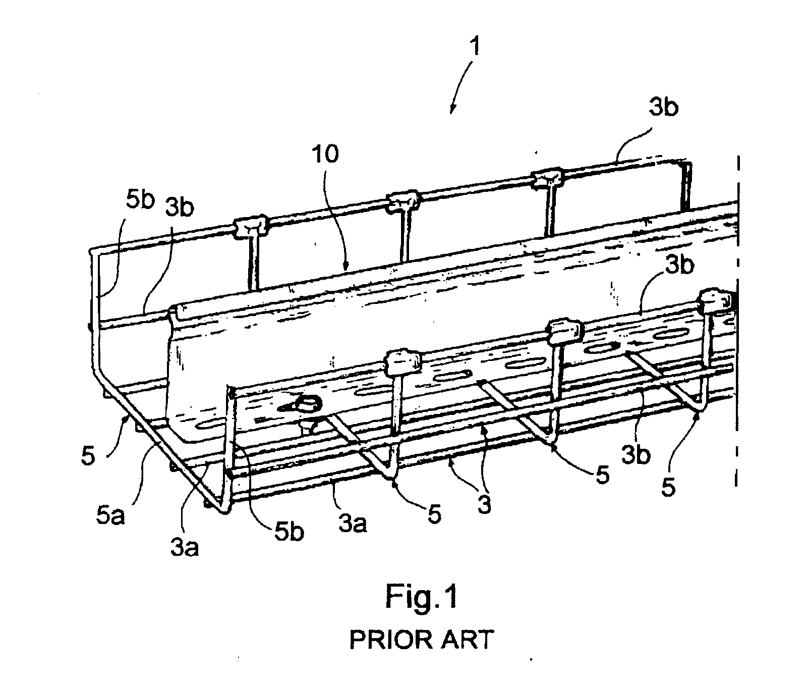
[0028]FIG. 1, which has already been mentioned in the introductory portion of this description with reference to the prior art, shows a cable duct 1 of the type generally known as a “mesh duct”, comprising a series of longitudinal wires 3 and a series of tra...


PUM


Abstract

The separator element can be coupled releasably with a mesh cable duct and is suitable for dividing the cable-housing space along at least a portion of the duct into a pair of adjacent longitudinal compartments. The separator element is formed by a wire which is bent in a manner such as to be coupled with a mesh of the base of the mesh cable duct and to have a portion which projects into the cable-housing space.

Description

BACKGROUND OF THE INVENTION [0001] The present invention relates to cable-duct systems for industrial ducting and, more particularly, to mesh cable-ducts. Specifically, the invention relates to a separator element for a mesh cable duct of the type defined in the preamble to Claim 1. [0002] A separator element is used conventionally inside a cable duct to comply with circuit-separation, electromagnetic-insulation or cable-arrangement requirements. [0003] A separator may be used for physical separation between cables of ordinary circuits and cables of safety circuits when they are all installed in the same duct, in order to conform to the installation standards which require the safety circuits to be independent of the other circuits so that an electrical breakdown, an intervention, or a modification in an ordinary circuit does not compromise the operation of the safety circuits. [0004] A metal separator is used to comply with predetermined requirements for the electromagnetic compati...

Claims


Application Information

Patent Timeline
Patent Type & Authority Applications(United States)
IPC IPC(8): F16L3/00
CPCH02G3/0443
Inventor SPAGNOLI, GIAN PIEROFINCO, ALAN
Owner LEGRAND ZIBIDO SAN GIACOMO
Why Eureka
Try Eureka