Communication apparatus for vehicle

a technology for communication equipment and vehicles, applied in the direction of anti-theft devices, program control, instruments, etc., can solve the problems of short battery life, high frequency of battery replacement, and need to build oscillating circuits, so as to reduce the size and cost of portable units

Active Publication Date: 2007-02-08
MITSUBISHI ELECTRIC CORP
View PDF8 Cites 15 Cited by
  • Summary
  • Abstract
  • Description
  • Claims
  • Application Information

AI Technical Summary

Benefits of technology

[0018] Accordingly, the present invention is intended to solve the problems as referred to above, and has for its object to obtain a communication apparatus for a

Problems solved by technology

In the conventional communication apparatus for a vehicle, there is a problem that the oscillation circuit need be built in the portable unit, and a power supply and a power supply circuit for driving a transmission and reception circuit (the oscillation circuit, the modulation circuit and the demodulation circuit), the microcomputer and the memory are also required.
In particular, though a battery can be used as the power supply for the po

Method used


Image

  • Communication apparatus for vehicle
  • Communication apparatus for vehicle
  • Communication apparatus for vehicle

Examples


embodiment 1

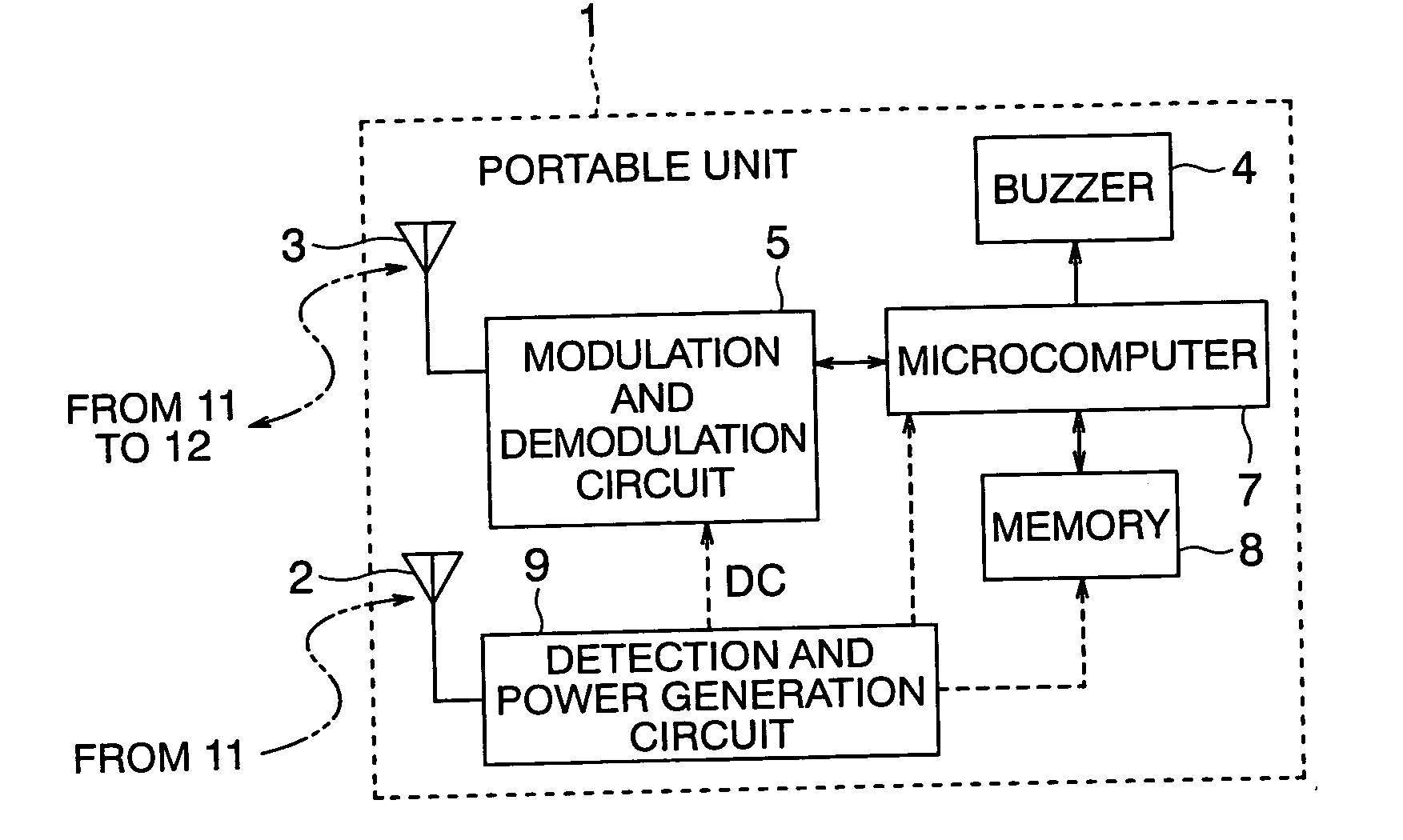
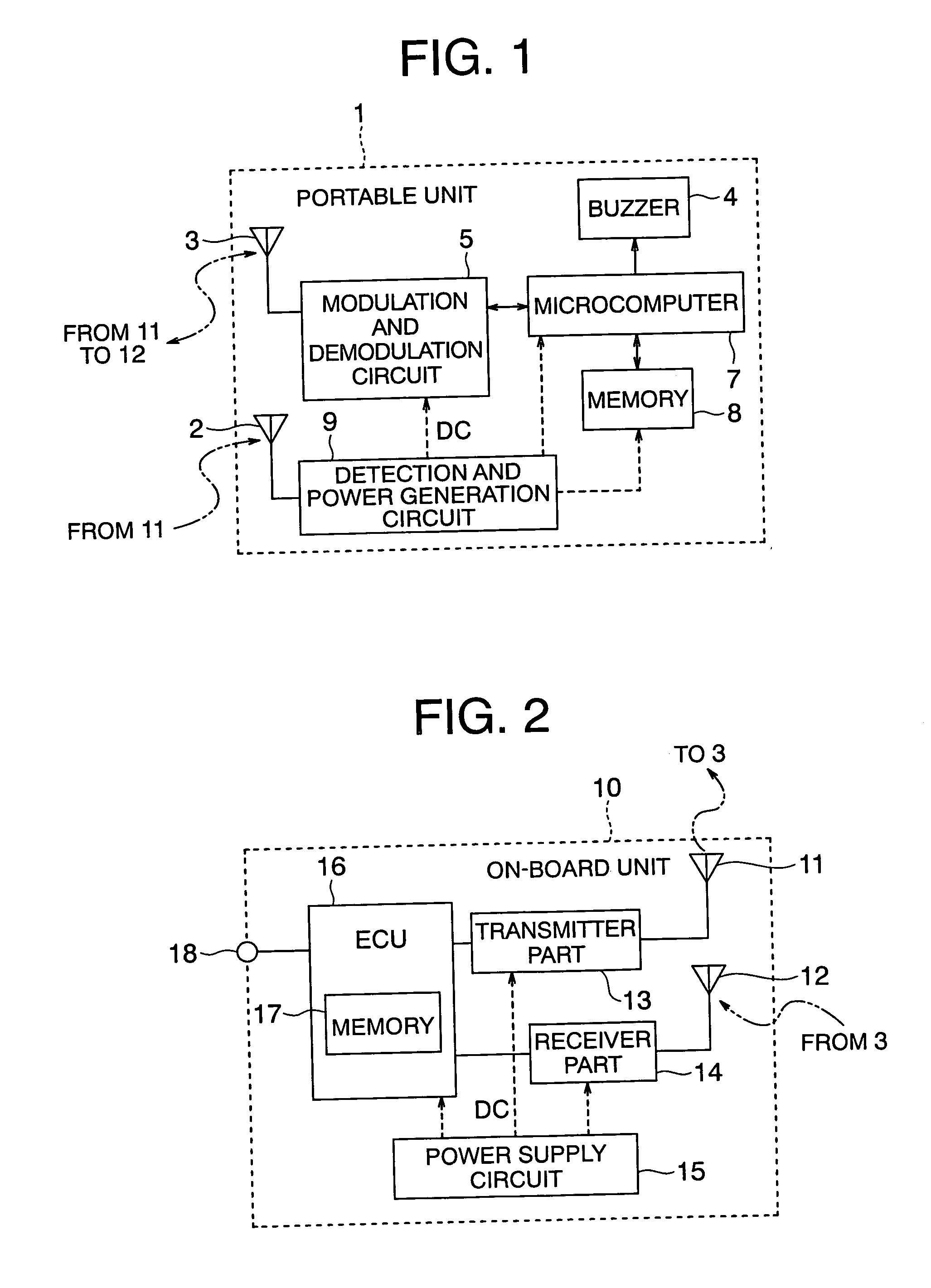
[0028]FIGS. 1 and 2 are block diagrams showing a communication apparatus for a vehicle according to a first embodiment of the present invention, wherein FIG. 1 shows the block configuration of a portable unit, and FIG. 2 shows the block configuration of an on-board unit.

[0029] In FIG. 1, the portable unit, generally designated at a reference numeral 1, includes a power generation receiving antenna 2, a transmitting and receiving antenna 3 for authentication (hereinafter referred to as an authentication transmitting and receiving antenna), a modulation and demodulation circuit 5 (including a modulation circuit for transmission and a demodulation circuit for reception) connected to the authentication transmitting and receiving antenna 3, a microcomputer 7 connected with the modulation demodulation circuit 5, a memory 8 belonging to the microcomputer 7, and a detection and power generation circuit 9 connected to the power generation receiving antenna 2. The authentication transmitting...

embodiment 2

[0050] Though not particularly mentioned in the above first embodiment, it may be possible to specify the position of the portable unit 1 on the side of the on-board unit 10 based on a response signal (ID signal) from the portable unit 1.

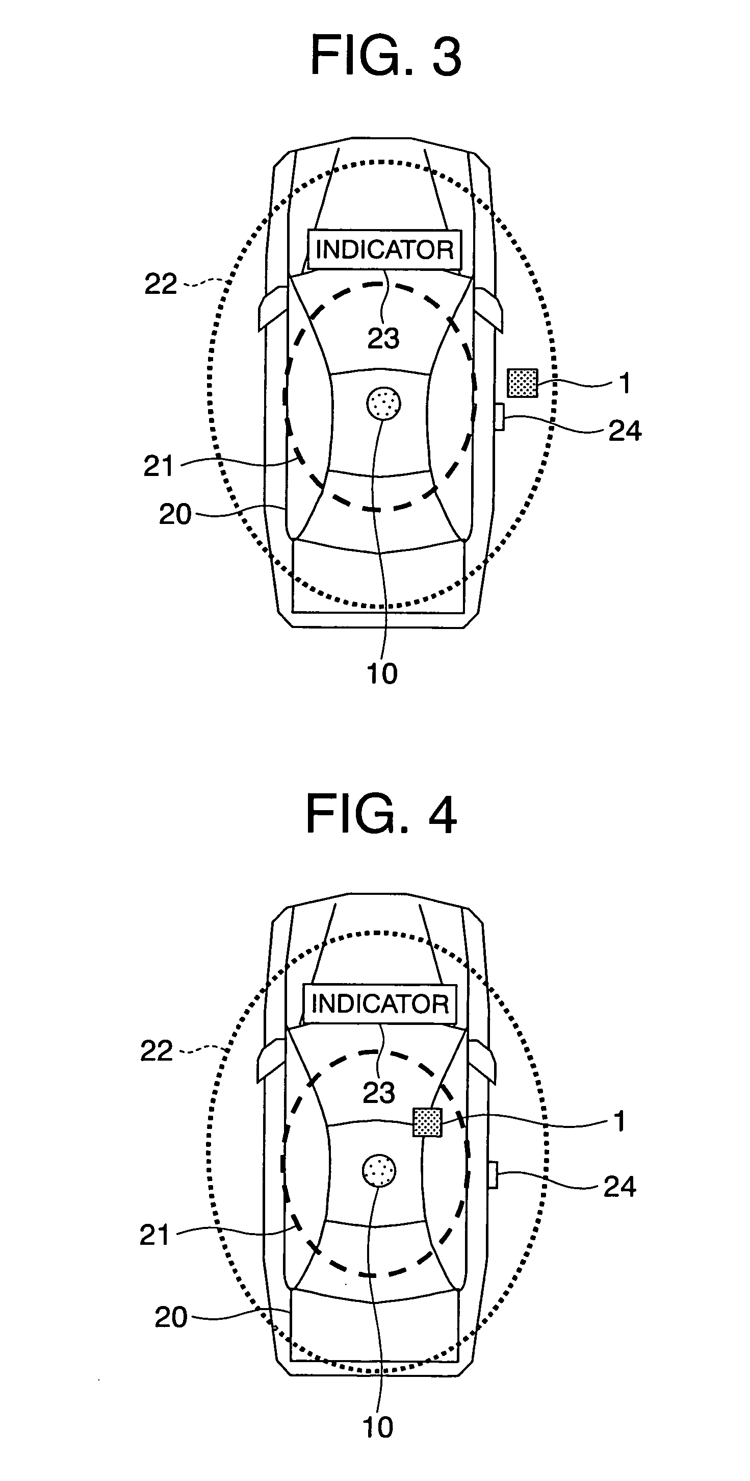
[0051] Hereinafter, reference will be made to a communication apparatus for a vehicle according to a second embodiment of the present invention in which the on-board unit 10 has a function of locating the position of the portable unit 1, while referring to FIG. 3 through FIG. 5.

[0052] In this case, the on-board unit 10 is constructed in such a manner that it sends or transmits a power generation radio wave and an authentication request signal for on-board device control to the portable unit 1 a plurality of times while changing the transmission power levels thereof, and specifies or locates the positions of the portable unit 1 at time points at which ID signals are received, based on the reception states of the ID signals from the portable unit 1 ...


PUM


Abstract

A communication apparatus for a vehicle achieves reduction in size and cost of a portable unit by making unnecessary an oscillation circuit and a battery in the portable unit. The apparatus is provided with an on-board unit installed on the vehicle and a portable unit carried by a user of the vehicle. A response signal is sent from the portable unit to the on-board unit in response to a signal transmitted from the on-board unit. The portable unit includes a power generation circuit for supplying electric power to circuits in the portable unit by a power generation radio wave sent from the on-board unit, and the on-board unit sends a communication signal after sending the power generation radio wave.

Description

BACKGROUND OF THE INVENTION [0001] 1. Field of the Invention [0002] The present invention relates to a communication apparatus for a vehicle that is adapted to be applied to a vehicular electronic key system, etc., and more particularly, it relates to a suitable technique when an electronic key is applied to a passive entry system in which the electronic key operates as a portable unit to lock and unlock doors of a vehicle in a simple and easy manner. [0003] 2. Description of the Related Art [0004] As a conventional communication apparatus for a vehicle, there has been known a vehicular lock control apparatus which uses an electronic key as a portable unit (see, for instance, a first patent document: Japanese examined patent application publication No. H03-60696). [0005] The vehicular communication apparatus or vehicular lock control apparatus as described in the first patent document is provided with a portable unit (transmitter-receiver) having a microcomputer and a memory built t...

Claims


Application Information

Patent Timeline
IPC IPC(8): G05B19/00B60R11/02B60R25/01B60R25/10B60R25/24B60R25/30B60R25/40E05B49/00
CPCB60R25/24G05B2219/36159G05B2219/33192
Inventor ONO, MASAYOSHISUMIDA, MASATOOOBA, TETSUYAKATAYAMA, MASAHIKOUEHARA, NAOHISA
Owner MITSUBISHI ELECTRIC CORP
Why Eureka
Try Eureka