Fiber optic gyroscope

a fiber optic gyroscope and fiber optic technology, applied in the field of fiber optic gyroscopes, can solve the problems of affecting the detection accuracy of optical fibers, the linear polarization of beam propagating through the coil is greatly susceptible to some influence to change, and the optical fiber maintains the plane of polarization much more expensive than a single-mode optical fiber, etc., to achieve the effect of high detection accuracy

Active Publication Date: 2007-02-08
JAPAN AVIATION ELECTRONICS IND LTD
View PDF7 Cites 17 Cited by
  • Summary
  • Abstract
  • Description
  • Claims
  • Application Information

AI Technical Summary

Benefits of technology

[0022] With the arrangement of the present invention as described above, the angular alignment of 45° which is required to serve as a depolarizer can be achieved through a connection between the optical fibers, and this connection can be made by using a commercially available polarization maintaining optical fiber fusion connector which performs a fusion connection of the optical fibers while assuring that a desired relative angle can be accurately achieved through an image analysis when the stress applicators within the polarization maintaining optical fibers are laterally observed in an optical manner. This allows light beams which are assured to be in a properly non-polarized condition to be made incident on the opposite ends of the single mode fiber optic coil, resulting in a fiber optic gyroscope having a high accuracy of detection.

Problems solved by technology

However, an optical fiber which maintains the plane of polarization is much more expensive than a single mode optical fiber.
In a single mode fiber optic coil in which a single mode optical fiber is used as a fiber optic coil in consideration of such expensiveness, birefringence occurs, though slightly, when the coil is flexed, leading to the consequence that the linear polarization of the beam propagating through the coil is greatly susceptible to some influence to change.
However, it is found subsequently that the leaking TM mode beam not only impinges on the fiber optic coil as the TM mode beam, but is also converted into the TE mode before it impinges on the fiber optic coil, thus producing an adverse influence upon the original TE mode beam which has propagated through the optical waveguide to degrade the extinction ratio of the polarizer.
Above described difficulties involved with the use of a single mode fiber optic coil and the use of a substrate-based optical integrated circuit which has a combined function serving as a polarizer and a branching filter appear as a variation in the bias error of the fiber optic gyroscope.
Specifically, when no angular rate is applied, the fiber optic gyroscope should deliver a detection output of zero, but there is a detection output as a bias, and the bias error varies, thus degrading the accuracy of detection.
This means that if the polarization axis of each of the polarization maintaining optical fiber 18 or 21 is not disposed properly at an angle of 45° with respect to the direction of the electric field of the TE mode of the optical wave guide 15, a light beam which is incident on the single mode fiber optic coil 20 cannot be in an exactly non-polarized condition, leading to a degradation in the accuracy of detecting the angular rate.
However, the issue of the angular alignment when connecting the optical integrated circuit and the polarization maintaining optical fiber which is disposed toward the coil remains in the similar manner.

Method used


Image

  • Fiber optic gyroscope
  • Fiber optic gyroscope
  • Fiber optic gyroscope

Examples


Embodiment Construction

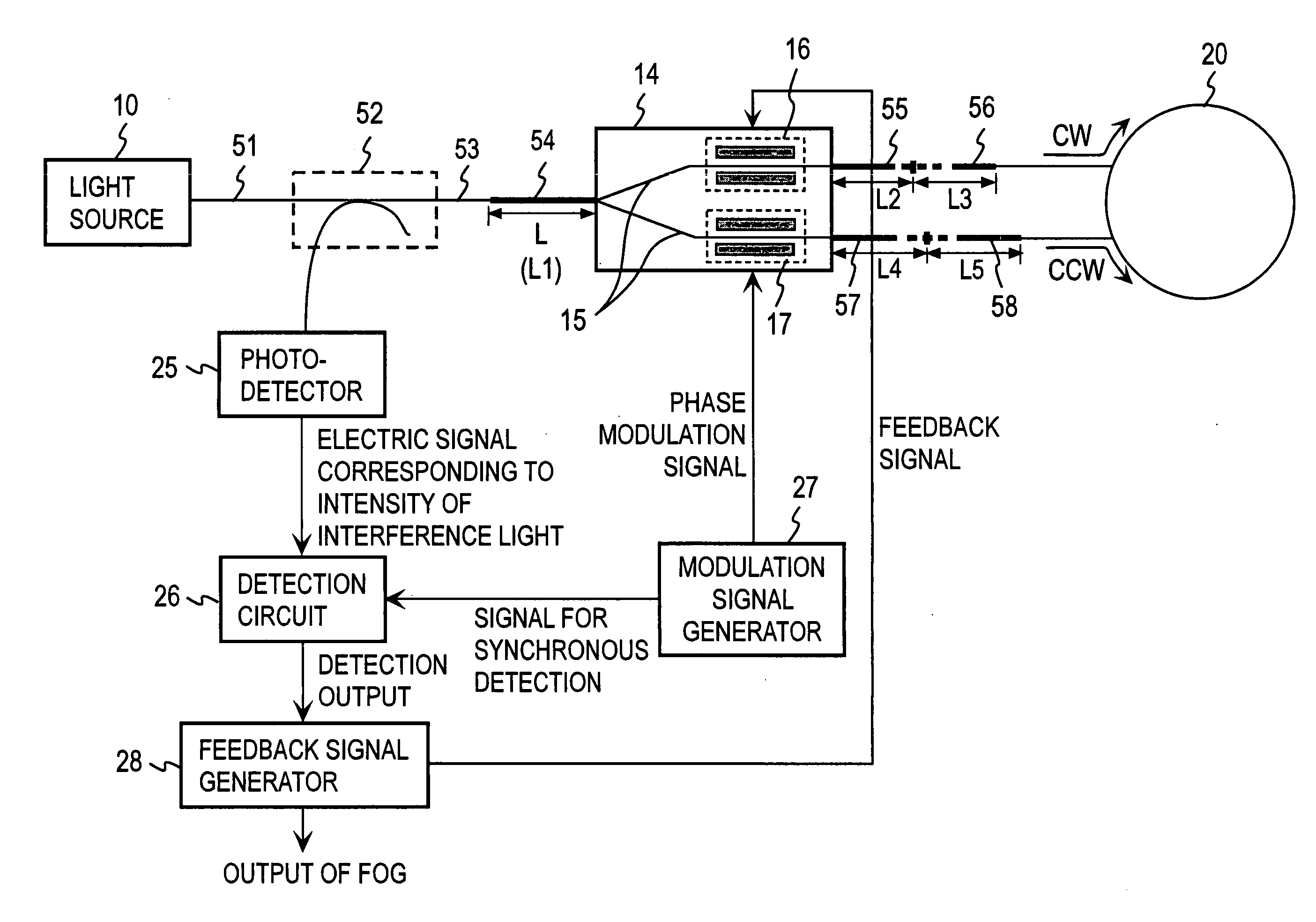
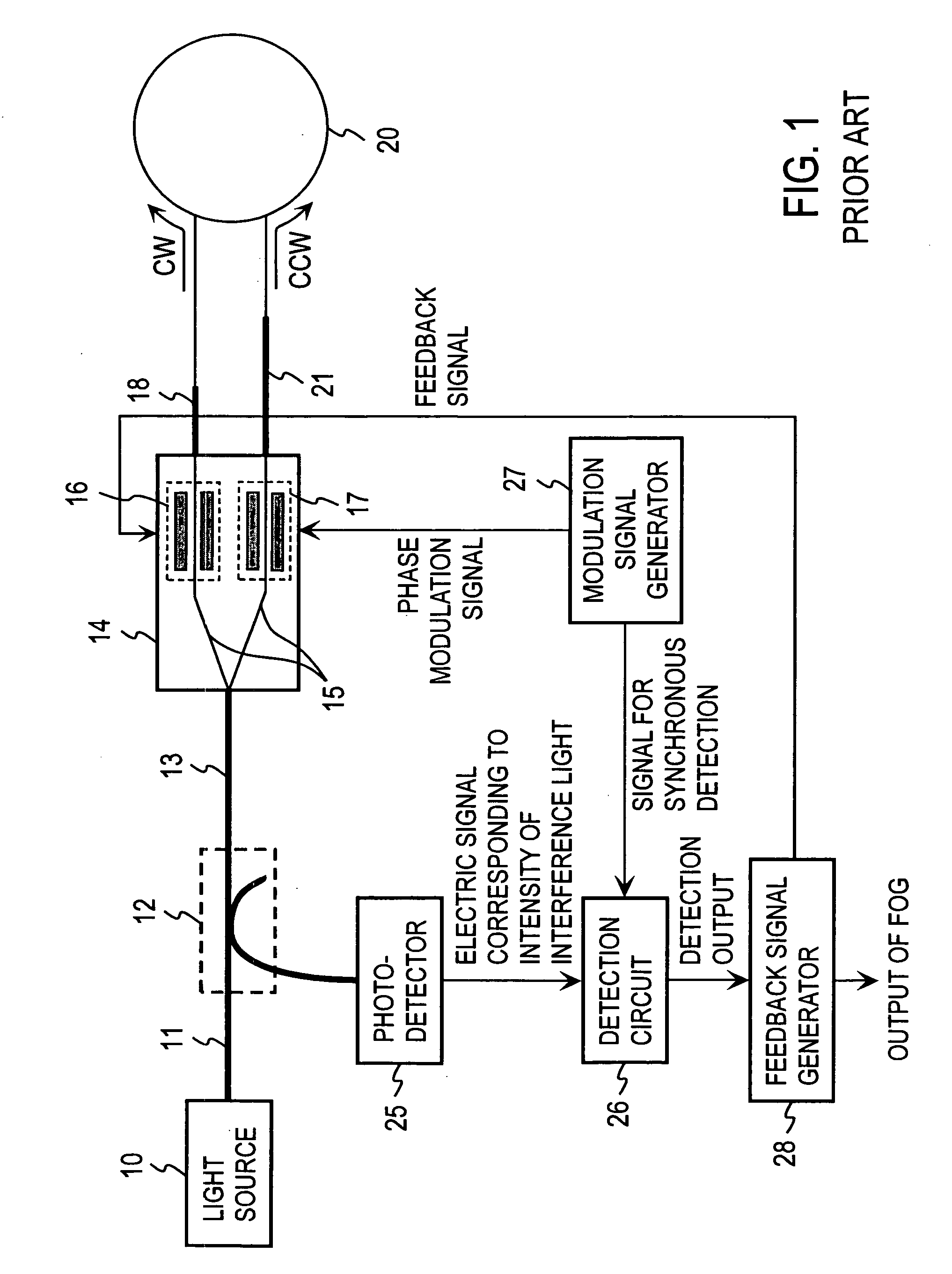
[0031] An embodiment in which the present invention is applied to a closed loop fiber optic gyroscope will now be described with reference to FIG. 4. It is to be noted that in FIG. 4, elements and parts corresponding to those shown in FIG. 1 are designated by like reference characters, and will not be described specifically unless otherwise required.

[0032] Light beam emitted from a light source 10 is passed through a first optical fiber 51, an optical fiber coupler 52, a second optical fiber 53 and a third optical fiber 54 to impinge on a substrate-based optical integrated circuit 14. In the present embodiment, the first and the second optical fiber 51 and 53 and the optical fiber coupler 52 are constructed with a single mode optical fiber while the third optical fiber 54 is constructed with a polarization maintaining optical fiber having a length L. The third optical fiber 54 has an polarization axis 33 which coincides with the direction of the electric field Ex of the TE mode in ...


PUM


Abstract

A light source 10 is connected sequentially through a single mode optical fiber and a coupler to one end of a polarization maintaining optical fiber, the other end of which is connected to an optical waveguide of an optical integrated circuit having a branching optical waveguide which has a polarizing function with the polarization axis of the optical fiber being coincident with the direction of the TE mode in the optical waveguide. One end of each of polarization maintaining optical fibers are connected to two other ends of the optical waveguide with the polarization axis of the optical fibers being coincident with the direction of the TE mode in the optical waveguide. The other ends of the optical fibers are connected to one end of each of polarization maintaining optical fibers with their polarization axis displaced by an angle of 45° from each other. The other ends of the optical fibers are connected to the opposite ends of a single mode fiber optic coil.

Description

BACKGROUND OF THE INVENTION [0001] The present invention relates to a fiber optic gyroscope including the function to serve as a polarizer and a substrate-based optical integrated circuit on which a branching optical waveguide is formed for detecting an angular rate about a coil axis which is applied to a fiber optic coil. [0002] In the fiber optic gyroscope, light beams impinge on opposite ends of the fiber optic coil, and propagate therethrough to be emitted from the opposite ends. A phase difference between the both emitted light beams remains to be zero when there is no angular rate which is applied to the fiber optic coil about the axis thereof. However, upon application of an angular rate, the phase difference between the both emitted beams changes in accordance with the angular rate applied. Hence, the angular rate applied to the fiber optic coil is detected by detecting the phase difference. When the fiber optic coil exhibits birefringence, a light beam which propagates thro...

Claims


Application Information

Patent Timeline
Patent Type & Authority Applications(United States)
IPC IPC(8): G01C19/72
CPCG01C19/721
Inventor OHNO, ARITAKAUSUI, RYUJI
Owner JAPAN AVIATION ELECTRONICS IND LTD
Why Eureka
Try Eureka