

Optical scanning apparatus and image forming apparatus
- Summary
- Abstract
- Description
- Claims
- Application Information
AI Technical Summary
Benefits of technology
Problems solved by technology
Method used
Image

Examples
Embodiment Construction
[0035] An optical scanning apparatus according to one embodiment of the present invention will now be described.
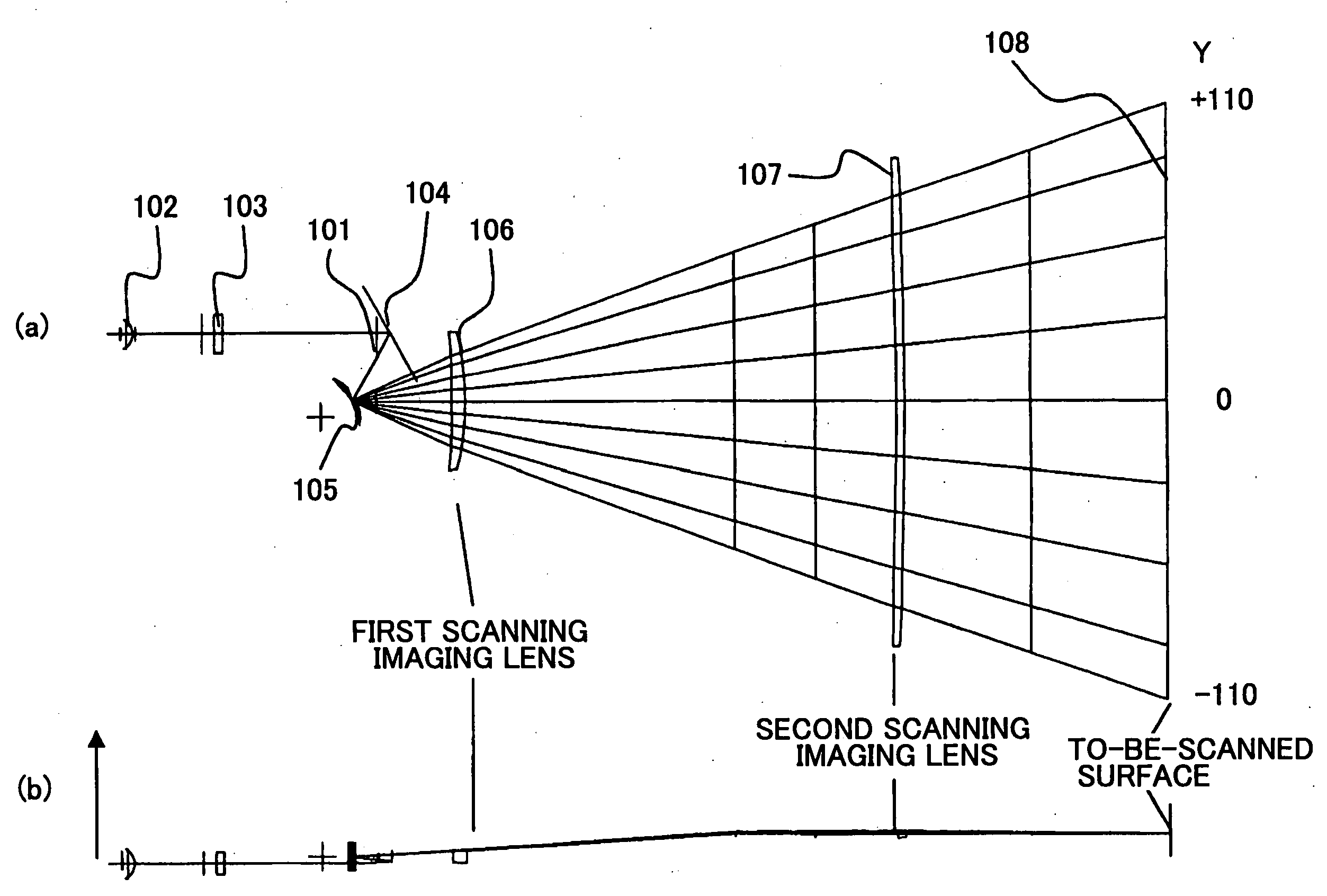
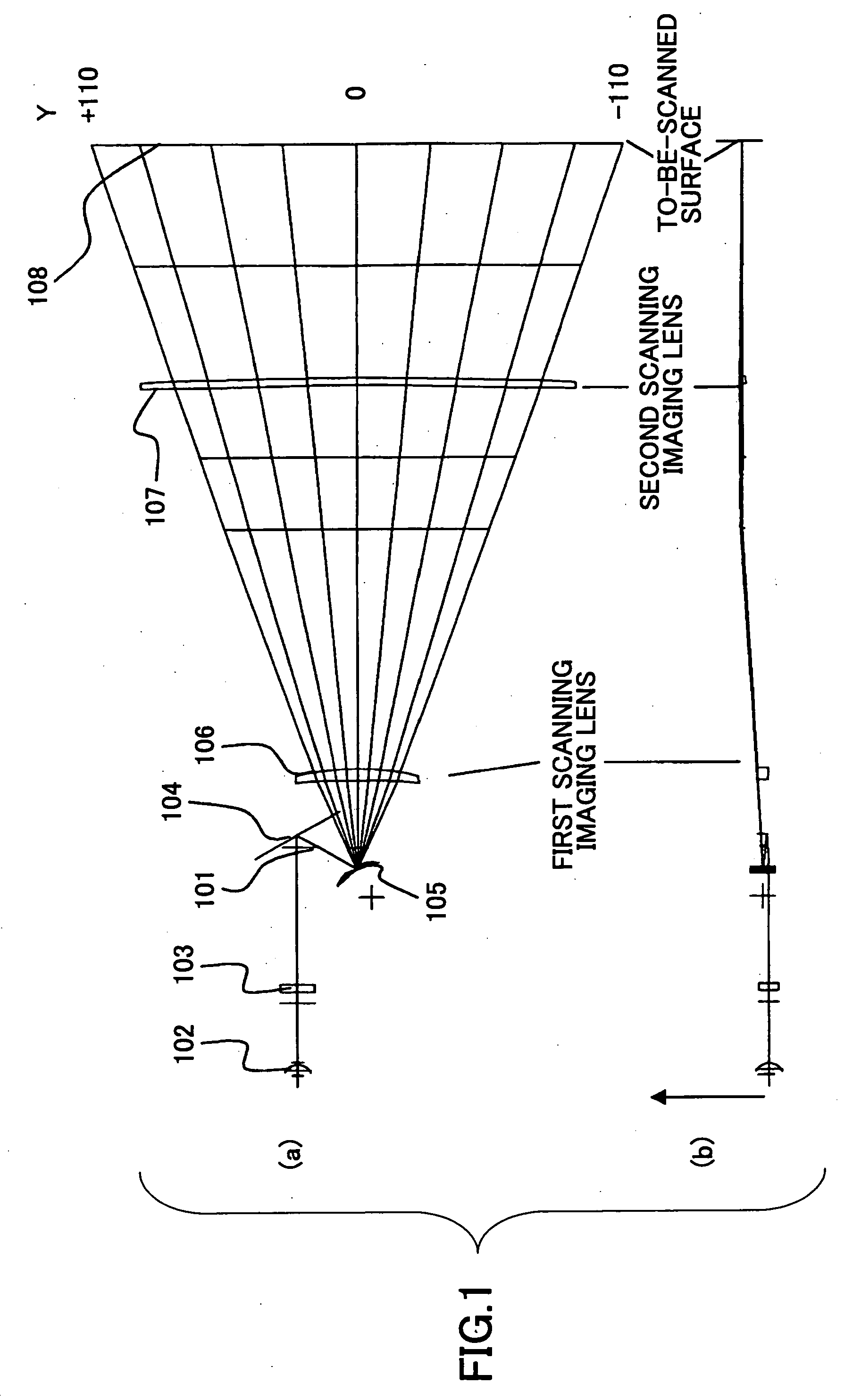
[0036]FIG. 1 shows a sectional view of the optical scanning apparatus in the embodiment of the present invention. FIG. 1(a) shows a sectional view of a main scanning direction and FIG. 1(b) shows a sectional view of a sub-scanning direction. As shown in FIG. 1(a), a diverging light beam 101 emitted by a semiconductor laser (light source) is transformed into a beam in a form suitable to a subsequent optical system by means of a coupling lens 102. The light beam in the form thus transformed may be a parallel light beam, a weak diverging light beam or a weak converging light beam. The light beam from the coupling lens 102 is condensed in the sub-scanning direction by means of a cylindrical lens 103, and is applied to a deflection reflective surface of an optical deflector 105 after being reflected by a reflective mirror 104. Then, passing through a first scanning imaging len...
PUM
 Abstract
Description
Claims
Application Information