System and method for fault protection for permanent magnet machines

a permanent magnet machine and fault protection technology, applied in emergency protection circuit arrangements, generation protection through control, lighting and heating apparatus, etc., can solve the problems of fixed rotor flux of pmms, pmms typically suffer major damage, and cannot be controlled or disengaged

Active Publication Date: 2007-02-08
HONEYWELL INT INC
View PDF7 Cites 44 Cited by
  • Summary
  • Abstract
  • Description
  • Claims
  • Application Information

AI Technical Summary

Benefits of technology

[0012] In yet another aspect of the present invention, there is provided a method for interrupting a short-circuit fault in a permanent magnet machine, wherein the permanent magnet machine comprises a plurality of windings and a neutral point, the method comprising the steps of detecting a short-circuit fault in at least one of the plural...

Problems solved by technology

A drawback, however, is that the rotor flux in a PMM is fixed and cannot be controlled or disengaged when a short circuit occurs.
The result is that PMMs typically suffer major damage when a short circuit occurs in the system, resulting from massive currents flowing through the windings and generating high temperatures that typically melt and burn the machine's components.
Therefore, a PMM may present a hazard in some applications leading to its limited use, particularly in the aerospace industry.
Another prior art system for short-circuit protection uses a dc contactor that isolates the load from the inverter so ...

Method used


Image

  • System and method for fault protection for permanent magnet machines
  • System and method for fault protection for permanent magnet machines
  • System and method for fault protection for permanent magnet machines

Examples


Embodiment Construction

[0023] The following detailed description is of the best currently contemplated modes of carrying out the invention. The description is not to be taken in a limiting sense, but is made merely for the purpose of illustrating the general principles of the invention, since the scope of the invention is best defined by the appended claims.

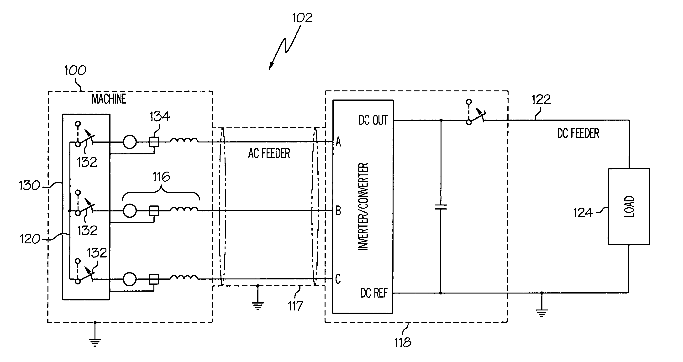
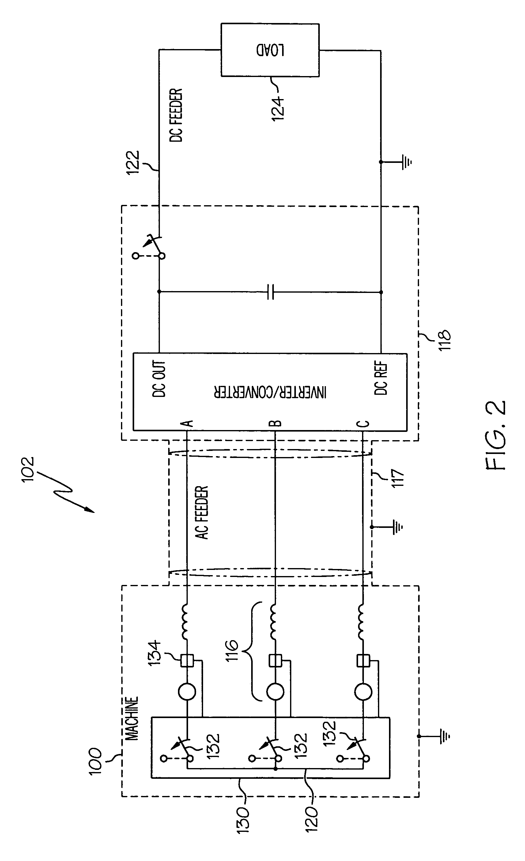
[0024] Broadly, the present invention provides a system and method of fault protection for permanent magnet machines (PMM) that utilizes machine neutral decoupling (MND) to shut down a shorted winding to prevent damage to the permanent magnet machine and to any downstream components, such as an inverter and a load. The invention may be used for high-reactance and low reactance PMMs, such as are commonly found in industrial and aviation applications.

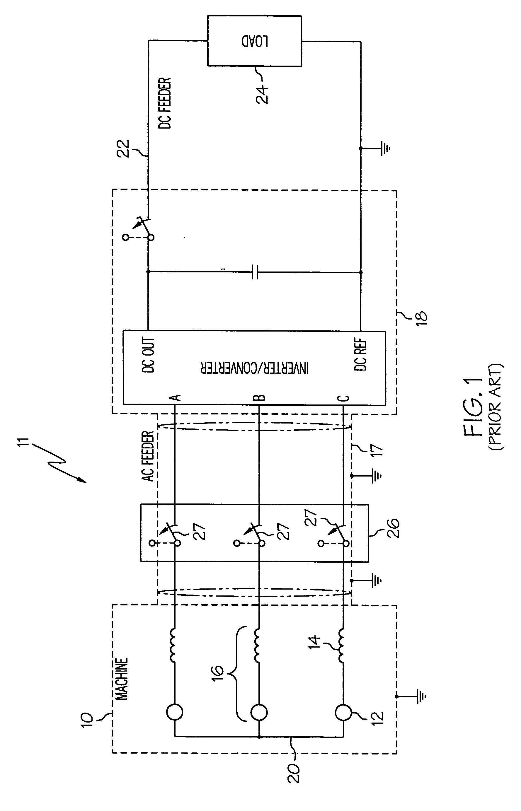
[0025] In contrast to the fault protection systems of the prior art, the present invention may interrupt a short-circuit current before it can damage the PMM and other components. The fault protection syst...


PUM


Abstract

A fault protection system and method of fault protection for permanent magnet machine (PMM)-based systems that utilize machine neutral decoupling (MND) to shut down a shorted winding and/or to isolate a short-circuit fault to prevent damage to a permanent magnet machine and to any downstream components are provided. The invention may be used for high-reactance and/or high current PMM-based systems, such as are commonly found in industrial and aviation applications.

Description

BACKGROUND OF THE INVENTION [0001] The present invention relates generally to fault-protection systems for machines where rotor flux cannot be controlled, and more particularly, to fault protection systems for synchronous permanent magnet machines. [0002] Permanent magnet machine (PMM) motors and generators are well known in the art. Such devices have windings that cut through the magnetic lines of force of a set of permanent magnets. The magnets may be arranged around a rotating set of windings or, conversely, windings may be arranged around a rotating magnet. [0003] PMMs are relatively inexpensive and easy to construct and outperform other designs in most applications. A drawback, however, is that the rotor flux in a PMM is fixed and cannot be controlled or disengaged when a short circuit occurs. Unlike other designs, such as wound-field (WF), induction, and switch-reluctance machines (SRM), where the excitation of the rotor flux may be controlled or shut down completely, a PMM co...

Claims


Application Information

Patent Timeline
IPC IPC(8): H02H7/08
CPCH02P9/006
Inventor GANEV, EVGENIBANSAL, MADAN L.WARR, WILLIAM H.
Owner HONEYWELL INT INC
Why Eureka
Try Eureka