Auxiliary circuit for use with three-phase drive with current source inverter powering a single-phase load
a current source inverter and auxiliary circuit technology, applied in circuit arrangements, power conversion systems, electric power transfer ac networks, etc., can solve the problems of reducing the reliability of the overall drive, input current, and the inability to have a standard design inverter drive, so as to reduce the harmonic of low-order curren
- Summary
- Abstract
- Description
- Claims
- Application Information
AI Technical Summary
Benefits of technology
Problems solved by technology
Method used
Image
Examples
first embodiment
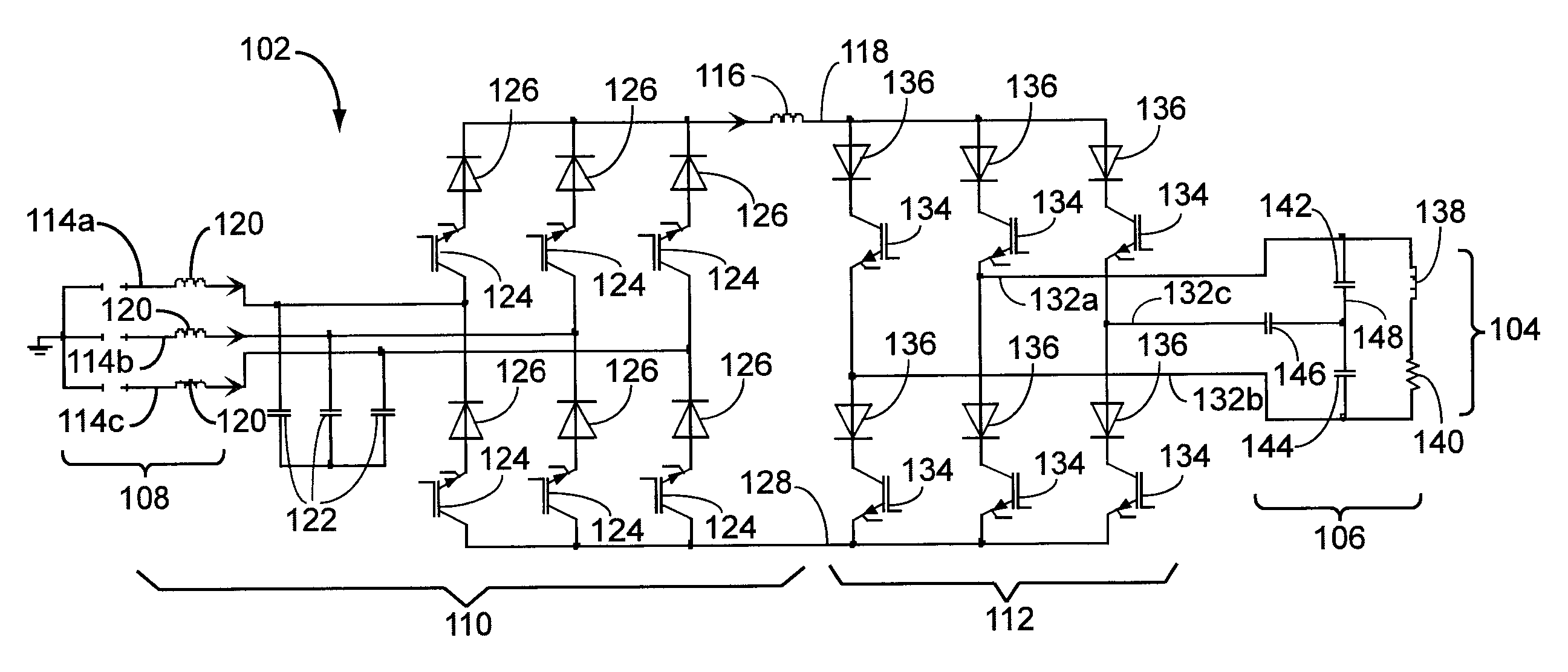
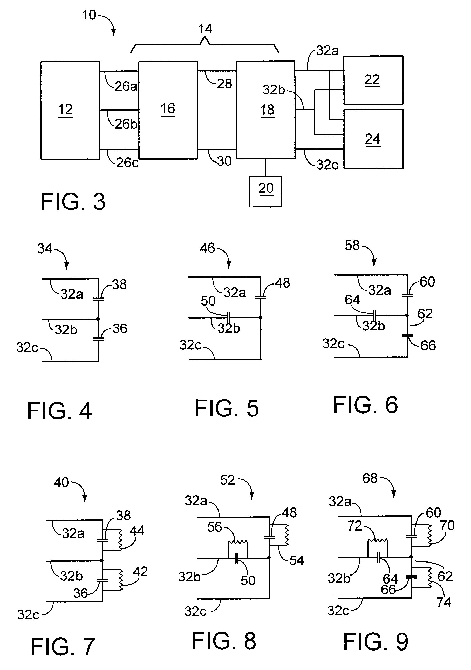
[0036] Referring now to FIGS. 4 and 7, in accordance with the invention, an auxiliary circuit 34 includes an auxiliary capacitor 36 connected to lines 32b and 32c. Auxiliary circuit 34 can further include a filter capacitor 38 connected to lines 32a and 32b (the same lines to which the single-phase load is connected). Auxiliary capacitor 36 and filter capacitor 38 may be paralleled with damping resistors 42 and 44 to form an auxiliary circuit 40 (see FIG. 7). Auxiliary circuits 34 and 40 are configured to compensate for single-phase load 22 driven by three-phase drive system 10 (as shown in FIG. 3). Capacitors 36 and 38 can be sized and configured to smooth out the PWM current generated by three-phase current source inverter 18. Damping resistors 42 and 44 can be sized and configured so as to dampen any unwanted harmonics and / or oscillations. The determination and calculation of the sizing of capacitors 36 and 38 will be discussed hereinafter.
[0037] Auxiliary circuit 34 can be desig...
second embodiment
[0051] Referring now to FIG. 5, in accordance with the invention, an auxiliary circuit 46 includes a first auxiliary capacitor 48 connected to supply lines 32a and 32c, and a second auxiliary capacitor 50 connected to supply lines 32b and 32c. As discussed hereinabove, single-phase load 22 is connected between supply lines 32a and 32b. First and second auxiliary capacitors 48 and 50 can be paralleled with damping resistors to form an auxiliary circuit 52 as shown in FIG. 8. Auxiliary circuit 52 includes a first auxiliary capacitor 48 and a parallel resistor 54 connected between supply lines 32a and 32c, and a second auxiliary capacitor 50 and a parallel resistor 56 connected between supply lines 32b and 32c. Design and sizing of first and second auxiliary capacitors 48 and 50 will be discussed hereinafter. Damping resistors 54 and 56 can be sized and configured so as to dampen any unwanted harmonics and / or oscillations.
third embodiment
[0052] Referring now to FIG. 6, in accordance with the invention, an auxiliary circuit 58 includes a first auxiliary capacitor 60 connected between supply line 32a and an auxiliary line 62, a second auxiliary capacitor 64 connected between supply line 32b and auxiliary line 62 and a third auxiliary capacitor 66 connected between supply line 32c and auxiliary line 62. As discussed hereinabove, single-phase load 22 is connected between supply lines 32a and 32b. Auxiliary capacitors 60, 64, and 66 can be paralleled with damping resistors 70, 72, and 74, respectively, to form an auxiliary circuit 68 as illustrated in FIG. 9. Design and sizing of the first, second and third auxiliary capacitors 60, 64, and 66 will be discussed hereinafter. Damping resistors 70, 72 and 74 can be sized and configured so as to dampen any unwanted harmonics and / or oscillations.
[0053] The design and sizing of auxiliary circuit 58 can be simplified similarly to the design and sizing of auxiliary circuit 34 by ...
PUM
 Abstract
Description
Claims
Application Information
 - R&D
- Intellectual Property
- Life Sciences
- Materials
- Tech Scout
- Unparalleled Data Quality
- Higher Quality Content
- 60% Fewer Hallucinations
Browse by: Latest US Patents, China's latest patents, Technical Efficacy Thesaurus, Application Domain, Technology Topic, Popular Technical Reports.
© 2025 PatSnap. All rights reserved.Legal|Privacy policy|Modern Slavery Act Transparency Statement|Sitemap|About US| Contact US: help@patsnap.com


