Industrial robot

a robot and industrial technology, applied in the field of industrial robots, can solve the problems of large robot size, inability to apply such a kind of cable harness to the rotary motion parts of the robot, and torn or broken individual electric wires, so as to improve the reliability of electric connections, maintain compactness of cable harnesses, and enhance the flexibility of the second bundl

Inactive Publication Date: 2007-02-08
FANUC LTD
View PDF3 Cites 19 Cited by
  • Summary
  • Abstract
  • Description
  • Claims
  • Application Information

AI Technical Summary

Benefits of technology

[0010] According to this invention, as a plurality of umbilical elements are flatly arranged parallel to each other in the first bundle of the cable harness and an individual umbilical element is bonded to the adjacent one with adhesive, the first bundle becomes compact and the individual umbilical elements are prevented from being entangled to each other. Also, as the plurality of umbilical elements in the second bundle of the cable harness are separate from each other, each of the umbilical elements is not restricted by the adjacent one to enhance the flexibility of the second bundle. Accordingly, the durability of the cable harness located in the rotary motion part is not disturbed to improve the reliability of the electric connections. Also, as a protector such as a cable track is unnecessary, the compactness of the cable harness can be maintained.
[0011] The present invention provides an industrial robot comprising at least one multi-core cable. According to this invention, while an outer diameter of the multi-core cable is large, a lateral width becomes smaller in comparison with a case wherein a plurality of single-core electric wires is flatly arranged. Accordingly, the compactness of the cable harness is more enhanced.
[0012] The present invention provides an industrial robot wherein the multi-core cable is a shielded cable. According to this invention, it is possible to carry out electromagnetic shielding of a plurality of electric wires at once, whereby the production of the shielded cables becomes easy. Also, the anti-noise proper...

Problems solved by technology

As the cable track 22 has a large radius of curvature, it is necessary to provide a large space within a robot, resulting in a problem in that the size of the robot is large.
To a cable arranged in a rotary motion part of the robot, however, a large tension is appl...

Method used


Image

  • Industrial robot
  • Industrial robot
  • Industrial robot

Examples


Embodiment Construction

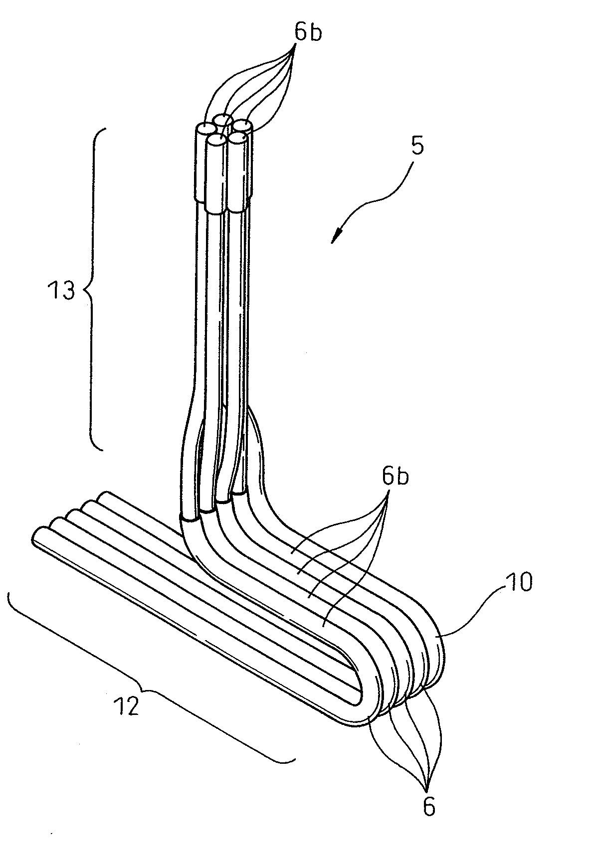
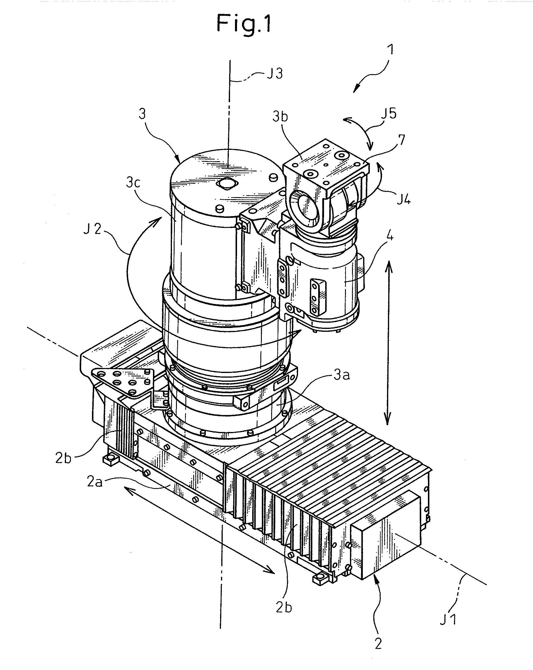
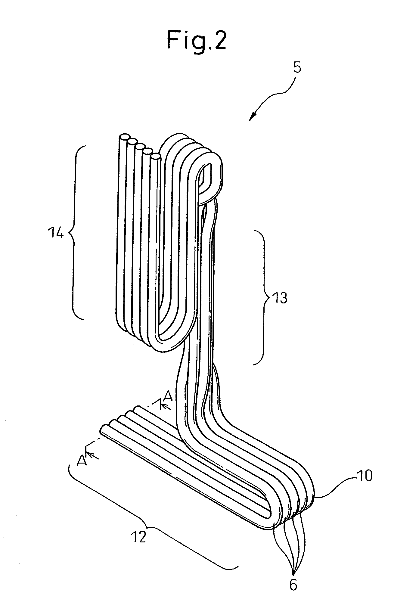
[0024] The present invention will be described in detail below with reference to the preferred embodiments shown in the attached drawings. FIG. 1 illustrates one embodiment of the inventive industrial robot, and FIGS. 2 to 6 illustrate a cable harness arranged in the industrial robot according to this embodiment.

[0025] As shown in FIG. 1, the industrial robot 1 according to this embodiment is an articulated robot for supporting a work piece, including a base (a linear motion part) 2 having a J1 axis as a linear motion axis, a J2 axis as a rotary motion axis and a J3 axis as a linear motion axis sequentially arranged from the base side to be subjected to the relative linear motion along the J1 axis, a body (a rotary motion part) 3 arranged vertically on the base 2 to be subjected to the relative rotary motion along the J2 axis, a cable harness 5 (FIG. 2) arranged in the base and the body 3, and equipments (not shown) such as a drive source or a controller for supplying electric powe...


PUM


Abstract

An industrial robot including a base carrying out a relative linear motion, a body carrying out a relative rotary motion and a cable harness for supplying electric power or transmitting control signals to operating circuits, wherein the cable harness includes a first bundle located in the base and a second bundle located in the body to be integral with the body, wherein, in the first bundle, a plurality of multi-core cables and tubes are flatly arranged parallel to each other and each of the multi-core cables and the tubes are bonded to the adjacent one with adhesive, and wherein, in the second bundle, the plurality of multi-core cables and tubes are separated from each other.

Description

BACKGROUND OF THE INVENTION [0001] 1. Field of the Invention [0002] The present invention relates to an industrial robot comprising a linear motion part relatively operable along a linear path, a rotary motion part relatively operable along a rotary path and a cable harness arranged in the linear motion part and the rotary motion part. [0003] 2. Description of the Related Arts [0004] Generally, an industrial robot having a plurality of motion axes comprises a linear motion part, a rotary motion part and a cable harness. There are two kinds of motion axes; one being a linear motion axis for relatively linearly operating, for example, two links with each other and the other being a rotary motion axis for relatively rotary operating the two links with each other. The linear motion axis and the rotary motion axis may often be incorporated in one robot. The linear motion part operates along the linear motion axis and the rotary motion part operates along the rotary motion axis, respectiv...

Claims


Application Information

Patent Timeline
IPC IPC(8): B66C23/00
CPCB25J19/0029
Inventor KUREBAYASHI, HIDENORIJINUSHI, MUNEHIRO
Owner FANUC LTD
Why Eureka
Try Eureka