Compaction vehicle

a technology of compact vehicles and levers, applied in the direction of machinery control, process and machine control, instruments, etc., can solve the problems of difficult operation of accurate levers, difficult effect of strict constant running, etc., and achieve the effect of improving the accuracy of running speed and running at a constant speed

Active Publication Date: 2007-02-08
SAKAI HEAVY INDS
View PDF9 Cites 8 Cited by
  • Summary
  • Abstract
  • Description
  • Claims
  • Application Information

AI Technical Summary

Benefits of technology

[0013] In accordance with the compaction vehicle it is possible to easily and surely run at a constant speed in a compaction construction. In addition, because the running speed output from the vehicle speed sensor becomes feedback control where the running speed is always reflected on the calculation device as feedback information, a maintaining accuracy of the running speed is improved in maintaining the memorized running speed.

Problems solved by technology

This accurate lever operation is difficult even for a skilled operator, and it can be said that a strict constant running is extremely difficult in effect.

Method used


Image

  • Compaction vehicle
  • Compaction vehicle
  • Compaction vehicle

Examples


Embodiment Construction

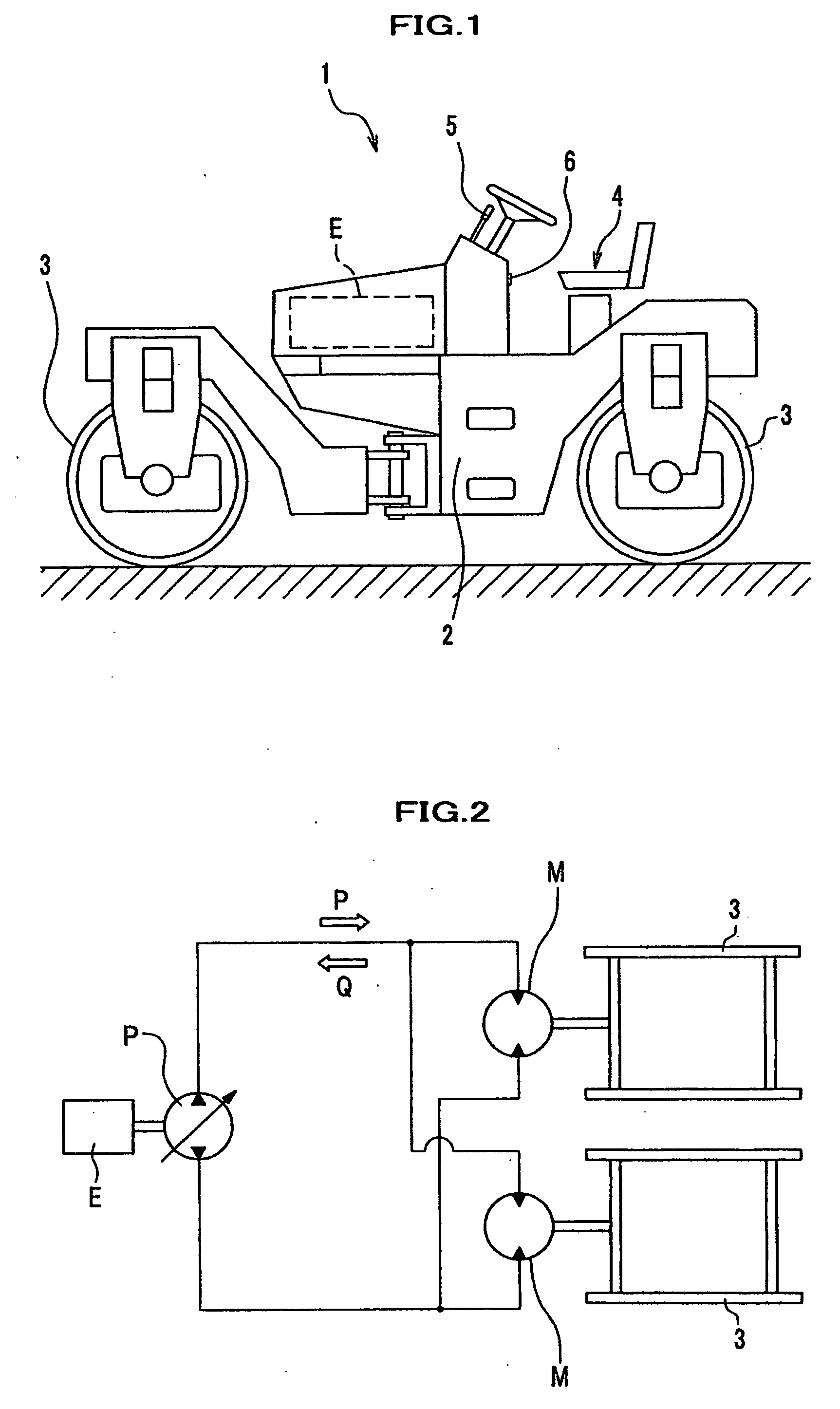
[0025]FIG. 1 is a side illustration drawing of a compaction roller that is an example of a compaction vehicle of the present invention. A compaction roller 1 comprises compaction wheels 3 in front and back of a vehicle body 2, and an engine E is mounted on the body 2. A driver's seat 4 is formed at the back of a mounting position of the engine E, and near the seat 4 is provided a forward / backward lever 5 having a function of running or stopping the compaction roller 1 at a neutral position (stop operation position), moving the roller 1 forward when tilted forward from the neutral position, and moving the roller 1 backward when tilted backward from the neutral position.

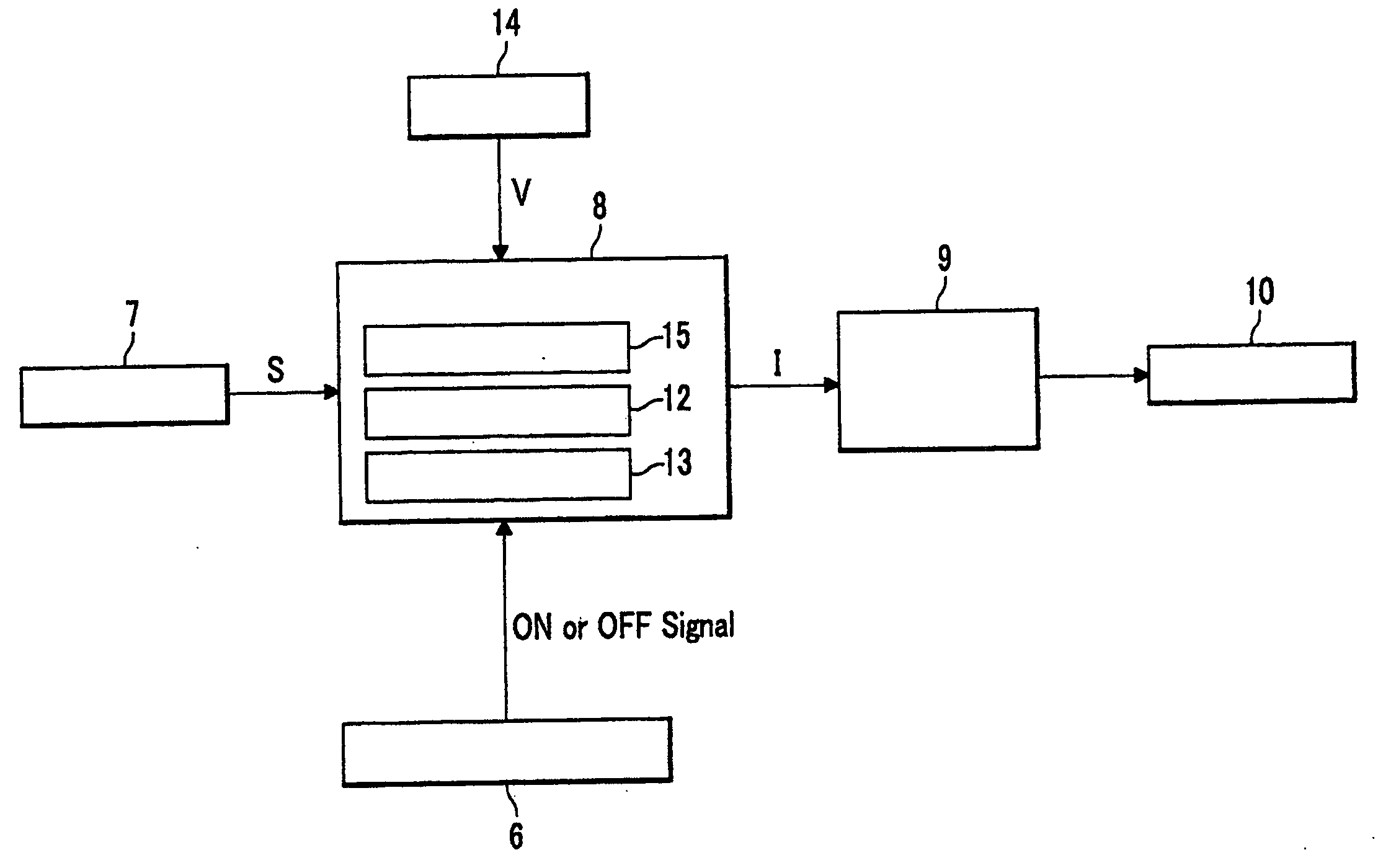
[0026]FIG. 2 is a schematic hydraulic circuit drawing related to a running system of the compaction roller 1. Symbol P is a variable displacement hydraulic pump rotated by the engine E. The hydraulic pump P corresponds to a running drive source 10 (FIG. 4) described later. Symbol M shows a running hydraulic motor that...


PUM


Abstract

The compaction vehicle having a speed adjustment member, a displacement detector, and a drive source controller further includes a calculation device between the displacement detector and the drive source controller, receiving the displacement S, and outputting a signal I calculated to the controller; a running speed setting switch for the operator operating ON at a desired running speed; a control signal memory device provided inside the calculation device and memorizing a signal I1 to the controller, wherein in a normal operation the calculation device outputs the signal I to the controller so that a running speed increases or decreases according to the displacement S, and wherein when the switch is operated to ON, the calculation device maintains the ON state, and the displacement S is not less than a predetermined value, the calculation device outputs the signal I1 memorized in the memory device so as to run the vehicle at a constant speed.

Description

BACKGROUND OF THE INVENTION [0001] 1. Field of the Invention [0002] The present invention relates to a compaction vehicle used in such a compaction construction of a road surface. [0003] 2. Description of the Related Art [0004] A compaction vehicle (for example, see FIG. 1 of Japanese Patent Laid-Open Publication No. 2002-342609) such as a compaction roller and a vibrating roller compacts a road surface by a compaction wheel, repeatedly moving forward and backward at a comparatively low speed. In a compaction construction by compaction vehicle, although there is a case that a vehicle running speed is made different according to such a kind of road surface material (such a kind of asphalt composite material), a temperature of the road surface material, an outside air temperature, a kind of vehicle, and a construction condition, a important matter in any running speed is to run the vehicle at a constant speed so that no variation occurs in a compaction density of the road surface. [00...

Claims


Application Information

Patent Timeline
Patent Type & Authority Applications(United States)
IPC IPC(8): G06F19/00E01C19/28
CPCE01C19/282E01C19/26
Inventor SUZUKI, SADAYOSHIMIYAMOTO, ISAMUTANAKA, SHINNOSUKE
Owner SAKAI HEAVY INDS
Why Eureka
Try Eureka