Liquid applying apparatus and ink-jet printing apparatus

a liquid application and inkjet printing technology, applied in printing presses, coatings, printing, etc., can solve the problems of difficult to employ the coating mechanism described in the above-mentioned documents to a small-sized apparatus, and the inability to obtain uniform coating films

Inactive Publication Date: 2007-02-15
CANON KK
View PDF15 Cites 32 Cited by
  • Summary
  • Abstract
  • Description
  • Claims
  • Application Information

AI Technical Summary

Benefits of technology

[0014] An object of the present invention is to provide a liquid applying apparatus and an ink-jet printing apparatus which can perform a coating oper

Problems solved by technology

Therefore, for example, if a coating medium with a relatively small size is intermittently conveyed for coating, a problem might occur that a uniform coated film can not be obtained because a coating bead is disturbed at the coating start or end position of each coating medium.
Therefore, vaporization of the coating liquid may cause a problem and when the attitude of the apparatus is changed, that might cause a problem of leakage of the coating liquid.
Particularly, in an ink-jet printing device as a printer, considering leakage of a liquid due to attitude change during transportation, the coating mechanisms described in the above each document are hard to be employed to a small-sized apparatus.
In the coating apparatuses as described in the above Japanese Patent Application Laid-open No. 2001-070858, Japanese Patent Application Laid-open No. 2002-517341, Japanese Patent Application Laid-open No. 8-072227 (1996) and Japanese Patent Application Laid-open No. 8-058069 (1996), a problem might occur which is caused by that the liquid for coating is kept at a certain location in the apparatus and does not flow for a relatively long time.
For example, if a coating operation is not performed for a relatively long time, the coating liquid remaining on the surface of the coating roller may become thick, and thus when the coating operation start again, the roller may not rotate normally or a medium can not be coated uniformly with the liquid.
However, in the Japanese Patent Appli

Method used


Image

  • Liquid applying apparatus and ink-jet printing apparatus
  • Liquid applying apparatus and ink-jet printing apparatus
  • Liquid applying apparatus and ink-jet printing apparatus

Examples


first embodiment

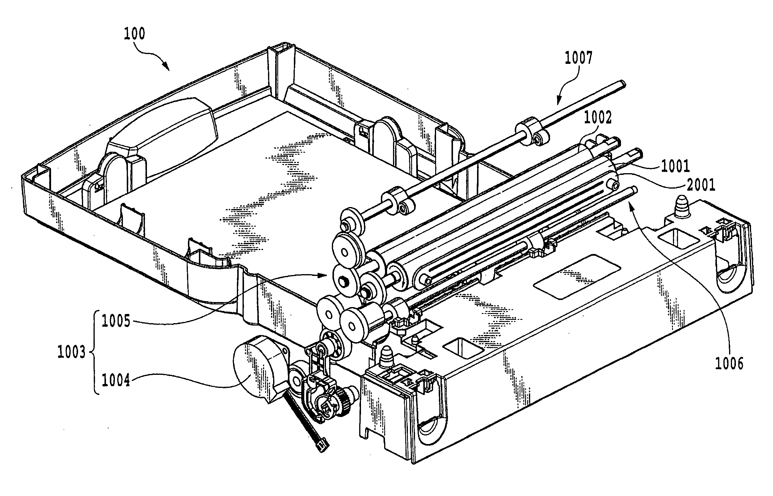
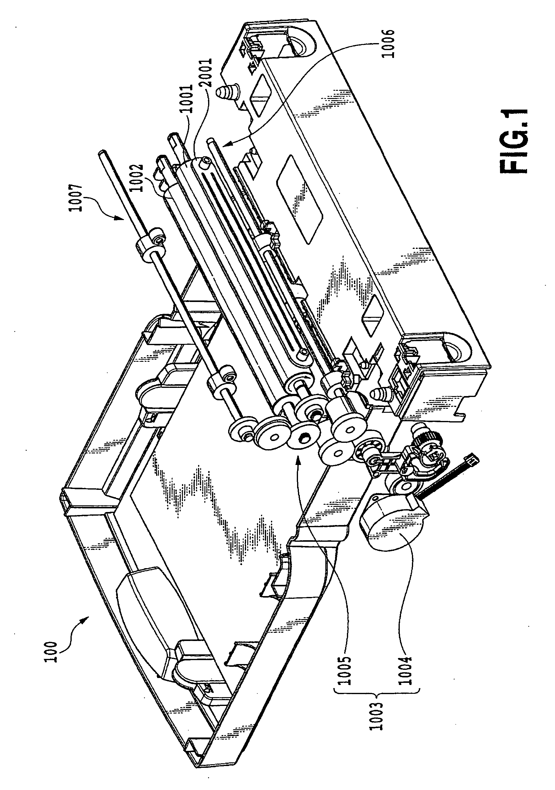
[0076]FIG. 1 is a perspective view showing an entire configuration of an embodiment of a liquid applying apparatus 100 according to the present invention. The liquid applying apparatus 100 shown herein is roughly configured to have a liquid applying mechanism for applying a predetermined applying liquid (also referred to as coating liquid hereinafter) to an applying medium (also referred to as coating medium hereinafter) and a liquid supplying mechanism for supplying the coating liquid to the liquid applying mechanism.

[0077] The liquid applying mechanism has a cylindrical applying roller (also referred to as coating roller hereinafter) 1001, a cylindrical counter roller (medium support member) 1002 arranged opposite to the coating roller 1001, and a roller driving mechanism 1003 for driving the coating roller 1001, or the like. The roller driving mechanism 1003 is composed of a roller driving motor 1004 and a power transmission mechanism 1005 having a gear train for transmitting a ...

second embodiment

[0138] A second embodiment of the present invention is relates to modes in which the pump operating speed is increased in the filling process when it is determined that the end process has not been performed and the driving speed of the coating roller is increased in the coating preparation operation of the coating roller. FIGS. 16 and 17 are flowcharts respectively showing details of the filling operation and the coating preparation operation. The other operations are the same as in the above described first embodiment.

[0139] [Filling Process]

[0140] In FIG. 16, first, the atmospheric air communication valve 3005 is opened and the reservoir tank 3003 is opened to the atmospheric air (Step S1011). Next, it is determined whether the flag is stored (set) or not by referring to the end process flag (Step S1012). If the end process flag is stored, it is determined that the recovering operation of the coating liquid has been carried out at the previous power off, and then the pump 3007 i...

third embodiment

[0148] A third embodiment of the present invention relates to modes in which the coating liquid with a possibility of increased viscosity due to non-recovering is re-fluidized by increasing the numbers of driving cycles of the pump and the coating roller, respectively, in the filling operation and the coating preparation operation of the coating roller if the recovering operation was not executed at the previous power off of the apparatus.

[0149]FIGS. 18 and 19 are flowcharts showing details of the filling operation and the coating preparation operation, respectively, according to this embodiment. The other operations are the same as those in the first embodiment.

[0150] [Filling Process]

[0151] In FIG. 18, first, the atmospheric air communication valve 3005 of the reservoir tank 3003 is switched to open the reservoir tank to the atmospheric air (Step S1021). Next, the end process flag is referred to (Step S1022) and if the end process flag is stored, it is determined that coating li...


PUM


Abstract

When it is determined that an end process flag is not stored in memory, there is a possibility that the recovery operation was not executed normally and the viscosity increased or fixed coating liquid exist in a liquid holding member and liquid flow paths. Therefore, a filling operation for generating stronger fluidization than a normal filling operation is carried out as a filling operation also acting as a restoration operation. That is, a pump is operated at a predetermined rotating speed for a specified time, which is longer than the specified time for the normal filling operation. By this, the viscosity increased coating liquid existing in the liquid holding space and the respective liquid flow paths is re-fluidized to an extent that will not interfere with circulation, and normal filling of the coating liquid is carried out.

Description

BACKGROUND OF THE INVENTION [0001] 1. Field of the Invention [0002] The present invention relates to a liquid applying apparatus and an ink-jet printing apparatus. More specifically, the present invention relates to a liquid applying apparatus for coating a medium with a liquid for a predetermined purpose such as facilitating coagulation of pigments when ink-jet printing with ink having the pigments as color material or the like. Also, the present invention relates to an ink-jet printing apparatus provided with a mechanism for applying a liquid to a printing medium for a purpose of facilitating coagulation of pigments at printing with ink having the pigments as color material. [0003] 2. Description of the Related Art [0004] As a method for widely applying a liquid or a liquid material to a medium, a spin coater, a roll coater, a bar coater and a die coater are known. These coating methods assume continuous coating on a coating medium with a relatively long length in the conveying di...

Claims


Application Information

Patent Timeline
IPC IPC(8): B05C11/00B05C5/00B41J29/393
CPCB41F31/027B41J2/175B41J29/17B41J11/0015B41J2/17509
Inventor NAKAGAWA, YOSHINORIIWASAKI, OSAMUMASUYAMA, ATSUHIKOOSHIO, NAOMIOTSUKA, NAOJI
Owner CANON KK
Why Eureka
Try Eureka