Eureka AIR delivers breakthrough ideas for toughest innovation challenges, trusted by R&D personnel around the world.

System for aerodynamic flows and associated method

a technology of aerodynamic flow and associated method, which is applied in the direction of airflow influencer, wing lift eficiency, drag reduction, etc., can solve the problems of significant amplitude, unsteady forces and moments, serious structural fatigue, etc., and achieves reduced viscosity, improved circulation, and improved stability.

Active Publication Date: 2007-02-15
THE BOEING CO
View PDF46 Cites 78 Cited by
  • Summary
  • Abstract
  • Description
  • Claims
  • Application Information

AI Technical Summary

Benefits of technology

[0010] Embodiments of the present invention address the above needs and achieve other advantages by providing a system for controlling boundary layer flow over an aircraft wing. The system employs fluidic devices to regulate fluid flow through ports that are in fluid communication with one another. As such, the ports and fluidic devices may be located in various locations on the multi-element aircraft wing to continuously control the boundary layer flow over the wing and reduce viscous effects. Results of computational fluid dynamics have shown that continuously regulating a plurality of linked ports results in more streamlined flow with higher circulation and reduced viscous effects. The aerodynamic improvement produces higher lift coefficient CL and reduced drag coefficient CD. Lift levels close to, and higher than, inviscid levels are achievable with this flow actuation.

Problems solved by technology

In addition, pulsed excitation results in unsteady forces and moments with significant amplitudes, which is detrimental to structural integrity and has serious implications to structural fatigue.
This is a particularly acute problem for a multi-element wing system where the slat and flap elements are deployed using systems of extendible linkages and tracks.
The quality of boundary layer control due to unsteady force and moment excitation is also limited with oscillatory actuators.
Furthermore, physical limitation of electrically driven actuators (diaphragm displacement, size of the orifice, and the size of the chamber) pose a limit on the maximum jet velocity and, thus, energy output.
Combustion actuators produce higher jet velocity, but their energy output is also limited because of their small orifice.
Moreover, the potential hazard of combustion-based systems poses a major obstacle to market acceptance by aircraft operators and the general public.

Method used


Image

  • System for aerodynamic flows and associated method
  • System for aerodynamic flows and associated method
  • System for aerodynamic flows and associated method

Examples


Embodiment Construction

[0033] The present invention now will be described more fully hereinafter with reference to the accompanying drawings, in which some, but not all embodiments of the invention are shown. Indeed, this invention may be embodied in many different forms and should not be construed as limited to the embodiments set forth herein; rather, these embodiments are provided so that this disclosure will satisfy applicable legal requirements. Like numbers refer to like elements throughout.

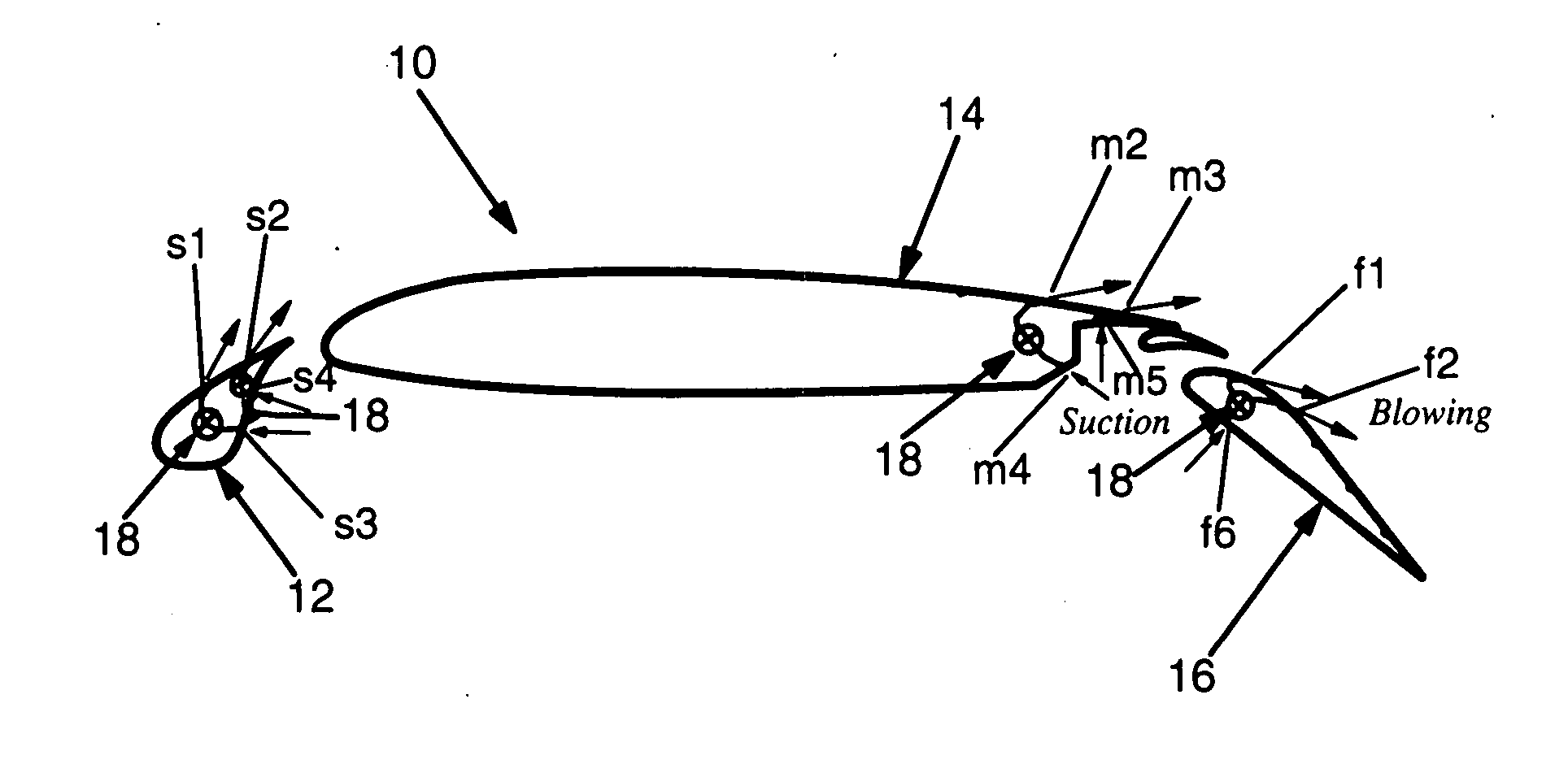
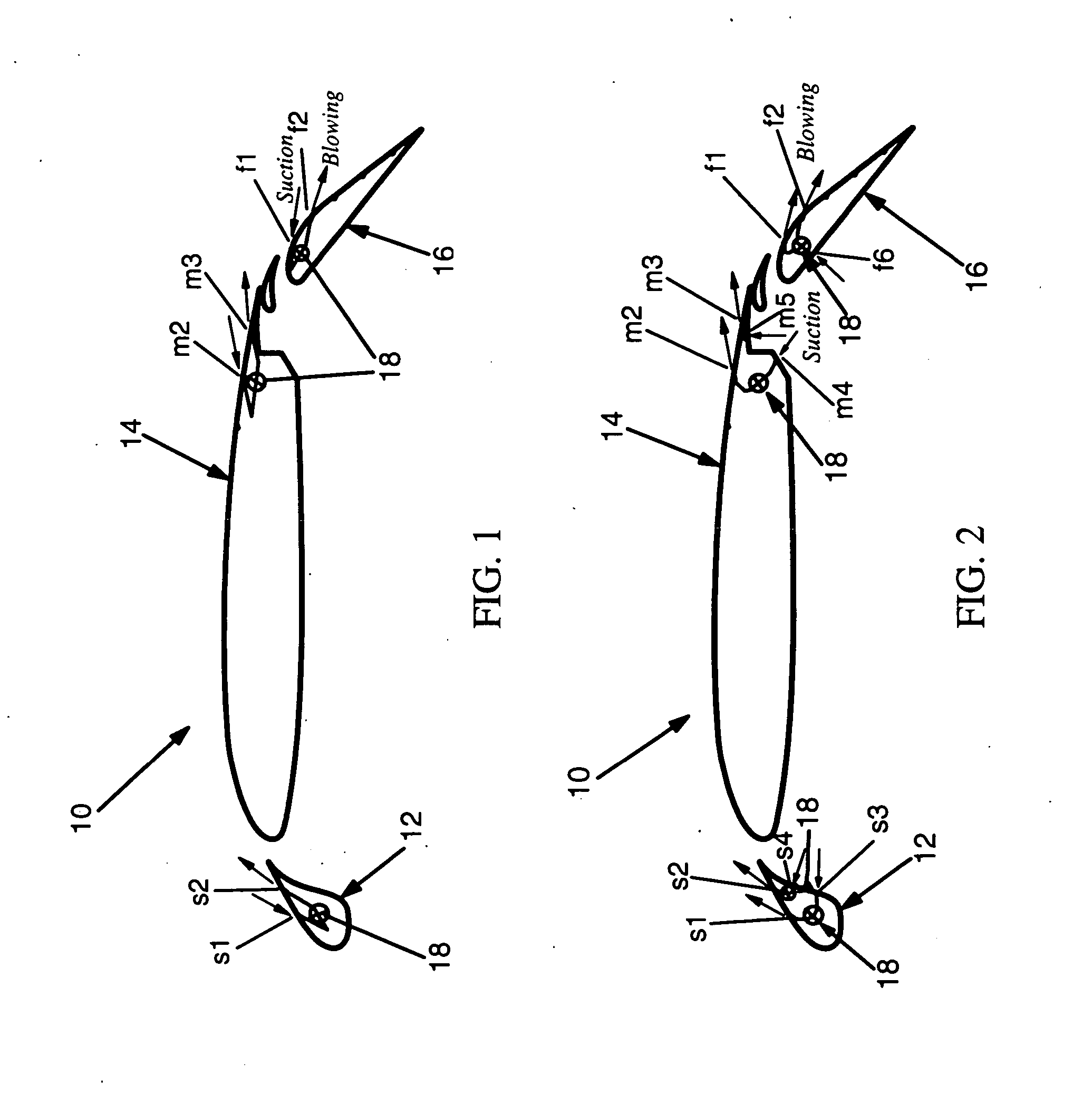
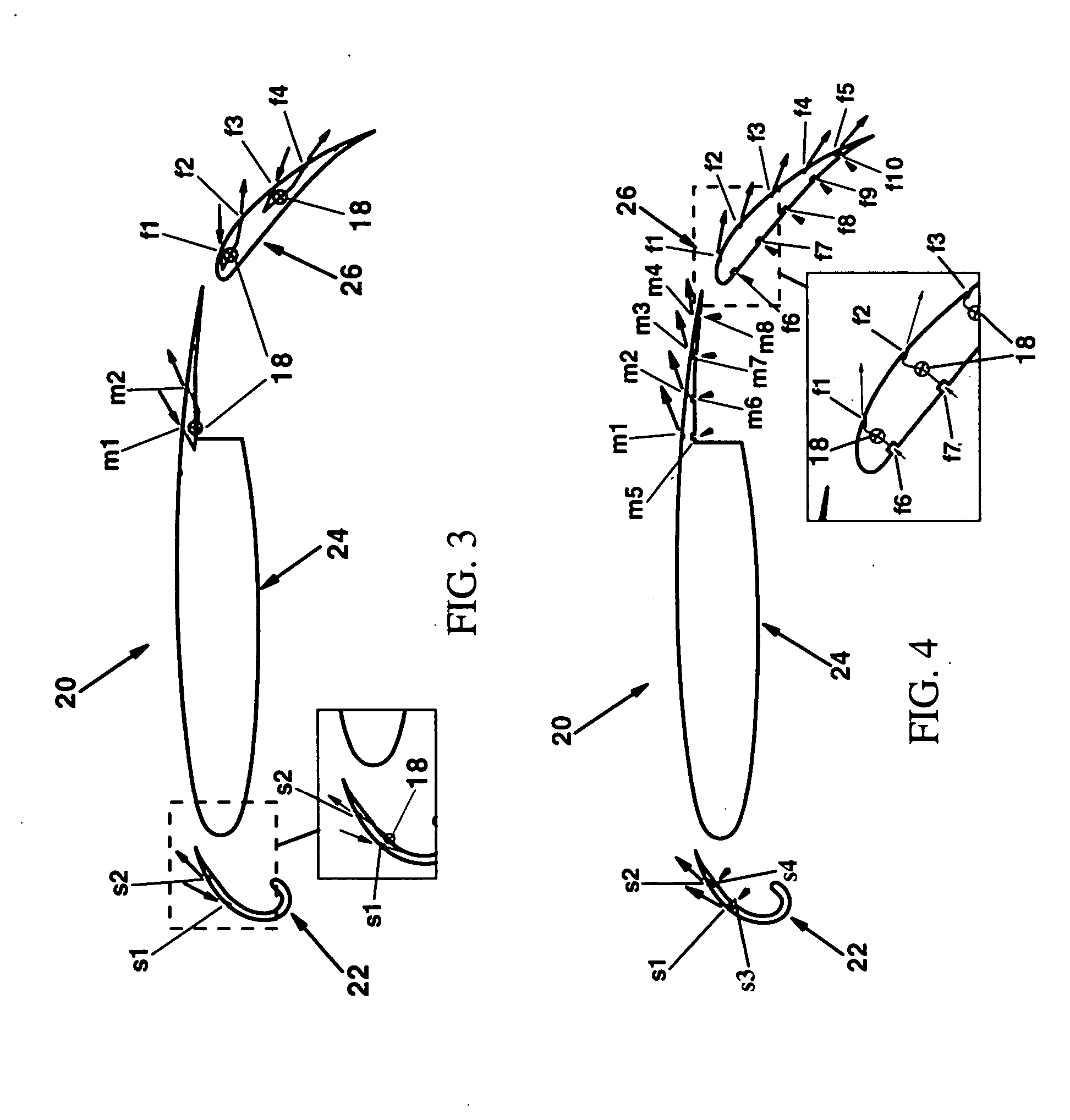
[0034] Referring now to the drawings and, in particular to FIG. 1, there is shown a system for controlling the boundary layer flow over a multi-element aircraft wing 10. The aircraft wing 10 generally includes a plurality of wing elements 12, 14, and 16. Each of the wing elements 12, 14, and 16 includes a plurality of ports defined therein. Fluidic devices 18 are utilized to regulate the flow of fluid into and out of the ports to control boundary layer flow over each of the wing elements 12, 14, and 16. Generall...


PUM


Abstract

A system and method for controlling boundary layer flow over an aircraft wing are provided. The system includes at least one wing element, and a plurality of ports defined in the wing element and in fluid communication with one another. The system also includes at least one fluidic device operable to continuously ingest the fluid through at least one of the ports and eject the fluid out of at least one other port to control boundary layer flow of the fluid over the wing element.

Description

BACKGROUND OF THE INVENTION [0001] 1) Field of the Invention [0002] The present invention relates to a system for aerodynamic flows and, more particularly, to a system capable of controlling boundary layer flow over an aircraft wing. [0003] 2) Description of Related Art [0004] One of the design objectives of the aircraft designer is to ensure high aerodynamic performance over a range of flight conditions. The performance during take-off and landing is a principal design objective of transport aircraft where high-lift capability is a key requirement. Take-off and landing are especially challenging since the flows are dominated by viscous effects, which are the major determinant of aerodynamic performance, and the ability to alter the characteristics of the viscous flow is vital to the development of efficient high lift systems. [0005] Techniques for altering the viscous flow structures are highly desirable due to the great potential for improved efficiency. A variety of fluidic actua...

Claims


Application Information

Patent Timeline
IPC IPC(8): B64C21/00B64C21/04B64C9/16
CPCB64C9/16B64C9/22B64C21/02B64C2230/04Y02T50/166Y02T50/32B64C2230/06B64C21/04Y02T50/30Y02T50/10
Inventor SHMILOVICH, ARVINYADLIN, YORAMCLARK, ROGER W.MANLEY, DAVID J.
Owner THE BOEING CO
Why Eureka
Eureka Blog
Learn More