
Systems and methods for removing lenses from lens molds

Active Publication Date: 2007-02-15
COOPERVISION INT LTD
View PDF62 Cites 133 Cited by
  • Summary
  • Abstract
  • Description
  • Claims
  • Application Information

AI Technical Summary

Benefits of technology

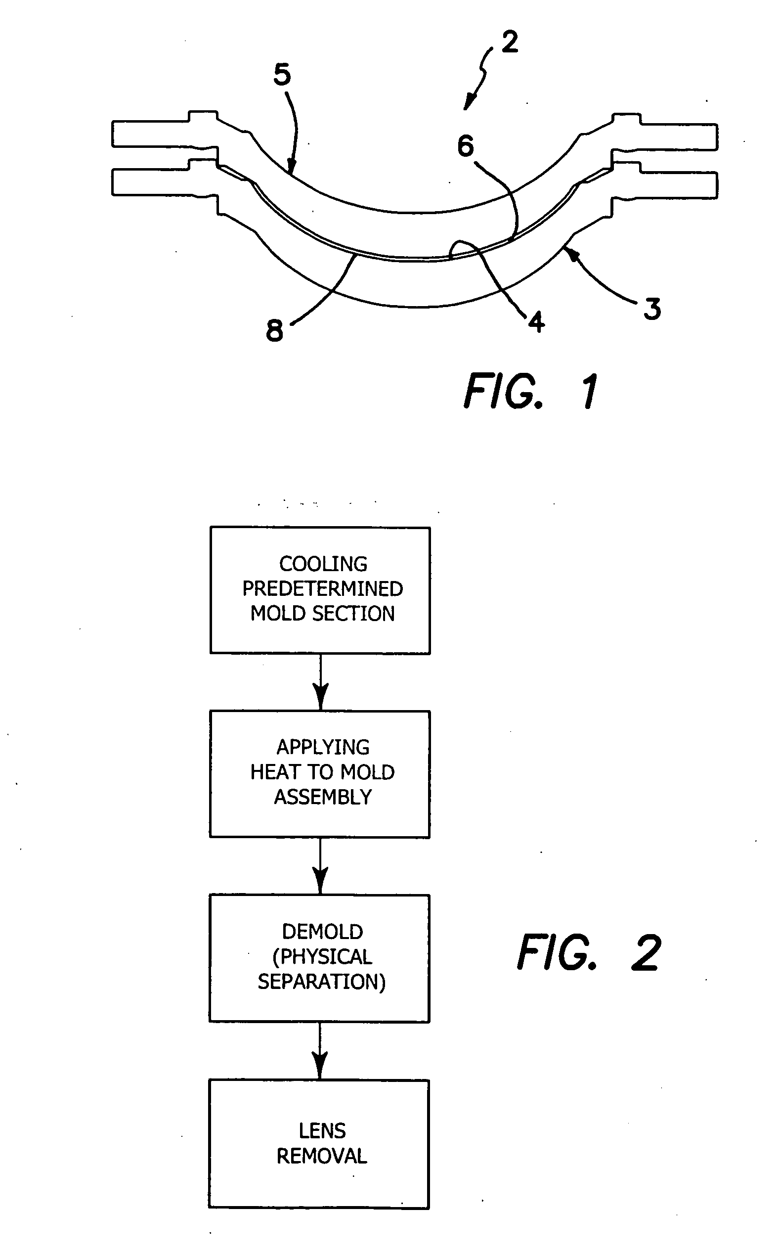
[0025] In some embodiments, the agent is applied to the predetermined mold section. The agent effectively draws heat from the mold section and causes the lens shaped article to become more firmly adhered to the lens shaped surface of the predetermined mold section.
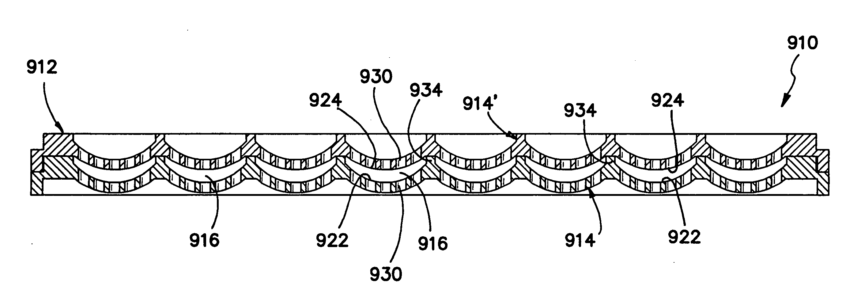
[0062] Very useful results are obtained when each of the trays comprises a polymeric material, for example, polypropylene homopolymer and the like polymeric materials, that is both suitable for use in an alcohol, e.g., ethanol-containing environment and has a low attenuation of ultrasonic energy which may be used during the fluid processing of the contact lenses to facilitate agitation of the fluids used in such processing. Such agitation or movement of the fluid facilitates mass transfer between the lenses and the processing fluids.

Problems solved by technology

Generally, lower thermal gradients created between the mold halves and the lens will require a greater force to separate the mold portions resulting in increased possibility of damaging a lens or fracturing a mold portion.
Using such a conventional vacuum system runs a substantial risk of damaging the contact lens and allowing liquid from or in contact with the lens to enter into the vacuum system, placing an added burden on such system.
This patent does not disclose or suggest removing a contact lens from a molding cup.
During such fluid processing, the lenses can become damaged, for example, by the fluid processing itself and / or as the lenses are moved between processing steps.
In addition, since a large number of different contact lenses, for example, contact lenses having one or more of different base curves, different refractive powers, different overall diameters, different cylinder corrections, if any, and the like differences, are often processed at the same time, such lenses can be misidentified after the processing.
Such misidentified lenses can result in added manufacturing costs, higher lens discard rates, and even mislabeling of the final lens product and / or providing the wrong lens to the ultimate consumer, the lens wearer.

Method used


Image

  • Systems and methods for removing lenses from lens molds
  • Systems and methods for removing lenses from lens molds
  • Systems and methods for removing lenses from lens molds

Examples


example

[0192] A tray of mold assemblies, each assembly containing a newly cured contact lens product, is received in a loading station. From the tray, pairs of mold assemblies are removed and placed in a nest located on a rotating disc. The pairs of mold assemblies are moved between various processing stations while they remain in the nest.

[0193] Each mold assembly is moved to a dipping assembly where the mold assembly is placed into a liquid bath containing deionized water at a temperature of 75° C. Ultrasound is radiated through the liquid bath to facilitate decoupling of the mold sections. The mold assembly is substantially entirely immersed in the liquid bath. Alternatively, the mold assembly is dipped in the liquid bath so that at least the mold section that includes the concave lens shaped surface (i.e. the “lens cup”) is in contact with the liquid. The mold assembly remains in the liquid for about 7 seconds. This liquid bath process functions to break or defuse bonded regions betwe...


PUM


Abstract

Methods and apparatus for separating mold sections, removing a lens product from the separated mold sections, and transferring the lens product to a processing tray are provided and include contacting assembled mold sections with a warm fluid to break fused portions between the mold sections, and using one or more wedge shaped elements to pry apart and separate the mold sections, one from the other. A vacuum head having multiple vacuum ports is employed for lifting the newly molded lens product from a mold section and for releasing the lens from the vacuum head into a processing tray. A cylinder of flowing air directed around the circumference of the lens is effective to maintain the lens in an unfolded position as the lens is being released into the processing tray. A tray set including multiple trays holding multiple lenses is provided and includes features for enabling visual and / or mechanical distinction of the trays and lenses held thereby.

Description

[0001] The present invention generally relates to the production of ophthalmic lenses, and more specifically relates to apparatus and methods for removing molded hydrogel contact lenses and the like, from the individual mold sections in which they are produced, and apparatus and methods for holding the removed contact lenses during processing of the lenses with one of more fluids. BACKGROUND [0002] As the ophthalmic lens industry has grown, it has become desirable to supply contact lenses that are periodically and frequently replaced to minimize the possibility of user induced contamination. This has produced an opportunity for manufacturers to strive for automated methods and apparatus that are able to automatically produce high quality ophthalmic lenses in a cost-effective and highly efficient manner. [0003] It is current practice in the art of making ophthalmic lenses, such as soft contact lenses of the hydrogel type, to form a monomer or monomer mixture that may be polymerized i...

Claims


Application Information

Patent Timeline
IPC IPC(8): B29D11/00B28B7/24
CPCB29D11/00221B29L2011/0041B29D11/0024G02B1/043B29D11/00067B29D11/00192B29D11/0023B29D11/0025B29D11/00
Inventor BRUCE, IANALMOND, SARAH L.BRAME, PHILIP A.BLYTH, GEOFFREY A.BLYTH, EVE
Owner COOPERVISION INT LTD
Learn More