Supercharge Your Innovation With Domain-Expert AI Agents!

Method and apparatus for detecting multiple overcurrent thresholds using a single comparator device

a comparator device and detection method technology, applied in the direction of dc motor speed/torque control, electric motor control, control system, etc., can solve the problems of reduced speed, high cost of multiple comparators for detecting multiple overcurrent thresholds, and circuitry used to detect overcurrent conditions must be extremely fast, so as to reduce the time taken to detect an overcurrent condition and reduce the system cost

Inactive Publication Date: 2007-02-15
INFINEON TECH AMERICAS CORP
View PDF4 Cites 12 Cited by
  • Summary
  • Abstract
  • Description
  • Claims
  • Application Information

AI Technical Summary

Benefits of technology

[0011] Disclosed herein are embodiments of a method and an apparatus that permit the detection of multiple overcurrent thresholds, providing the system protection advantages described above, but using only one comparator device instead of multiple comparator devices.
[0013] At least two advantages are provided by this invention. Firstly, the system cost is significantly reduced because only one comparator device is required to detect multiple overcurrent thresholds. Secondly, the time taken to detect an overcurrent condition is reduced because of the predictive nature of the invention.

Problems solved by technology

A first problem is that using multiple comparators for detecting multiple overcurrent thresholds can be expensive in cost-sensitive applications, such as but not restricted to electro-hydraulic power steering systems.
A second problem is that the circuitry used to detect overcurrent conditions must be extremely fast, but its speed is usually reduced by the amplifier and filter stage, which exhibits a propagation delay.
This propagation delay is unwanted because it could result in an overcurrent condition damaging the system before the system has time to detect the condition.
This propagation delay is unwanted, but is a by-product of the filtering that is used to remove electrical noise.

Method used


Image

  • Method and apparatus for detecting multiple overcurrent thresholds using a single comparator device
  • Method and apparatus for detecting multiple overcurrent thresholds using a single comparator device
  • Method and apparatus for detecting multiple overcurrent thresholds using a single comparator device

Examples


Embodiment Construction

The Apparatus:

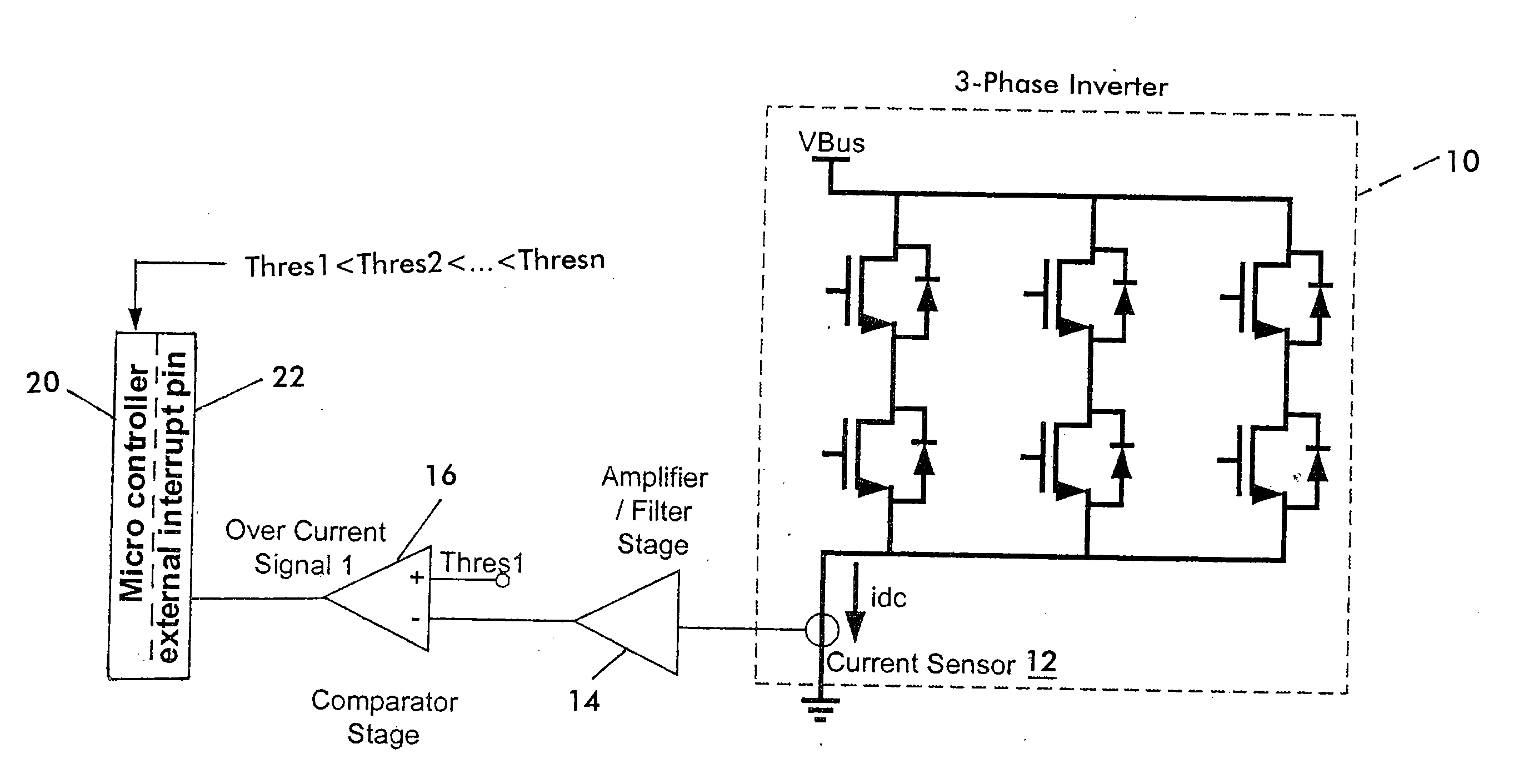
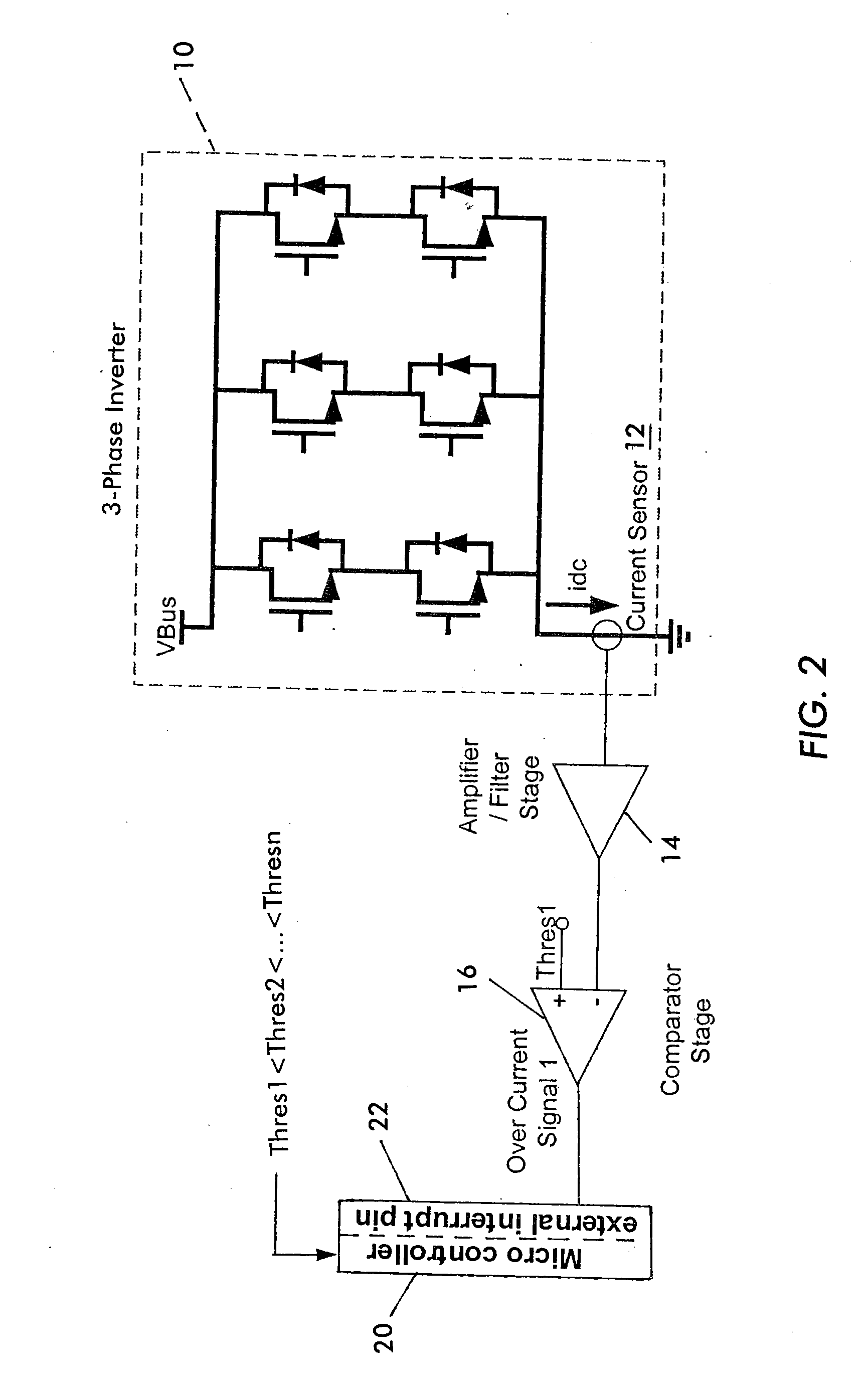
[0019] An apparatus which may be used to detect multiple overcurrent thresholds using a single comparator device is shown in FIG. 2. Again, like the solution of FIG. 1, it is desired to detect “n” different overcurrent thresholds Thres1, Thres2, . . . , Thresn, where Thres1216 which is set to detect the lowest overcurrent threshold (i.e. Thres1). The output of this single comparator may be routed to an external interrupt pin 22 of the microcontroller 20. The specific use of a microcontroller is advantageous, but not essential. It may be replaced by another device or equipment that is operable for carrying out the invention described herein.

The Method:

[0020] The microcontroller generates a pulse-width modulated (PWM) signal to turn the switches of the inverter 10 on or off in a specific sequence. Various techniques by which the inverter switches may be controlled to drive a brushless DC motor are well known to those in the art and need not be described in this docu...


PUM


Abstract

A method and an apparatus that permit the detection of multiple overcurrent thresholds, providing system protection particularly but not exclusively in brushless DC motor drive systems, but using only one comparator device instead of multiple comparator devices. The disclosed embodiments predict a higher overcurrent condition based on the time it takes to detect a lower overcurrent condition. Because of the predictive nature of the invention, the higher overcurrent conditions are detected much faster than when using conventional circuitry.

Description

CROSS REFERENCE TO RELATED APPLICATIONS [0001] This application is based upon and claims priority of U.S. Provisional Ser. No. 60 / 706,956 filed Aug. 10, 2005 (IR-3047 PROV), incorporated by reference.[0002] It is related to U.S. Provisional Ser. No. 60 / 706,962 filed Aug. 10, 2005 (IR-3046 PROV), and its corresponding U.S. non-provisional application, IR-3046 (2-5455), filed on even date herewith, also incorporated by reference. BACKGROUND OF THE INVENTION [0003] 1. Field of the Invention [0004] The present invention relates to a method and apparatus for detecting multiple overcurrent thresholds, and more particularly for detecting multiple overcurrent thresholds using a single comparator device. [0005] 2. Related Art [0006] In the design of brushless DC motor drive systems, there is often a requirement to sense the dc-link bus current. In brushless DC motor drive systems that are employed for safety-critical applications, such as but not restricted to electro-hydraulic power steerin...

Claims


Application Information

Patent Timeline
IPC IPC(8): H02P27/04
CPCH02M1/32H02P29/028H02M2001/0009H02P29/032H02M1/0009
Inventor QUIRION, JEAN P.
Owner INFINEON TECH AMERICAS CORP
Features
  • R&D
  • Intellectual Property
  • Life Sciences
  • Materials
  • Tech Scout
  • Unparalleled Data Quality
  • Higher Quality Content
  • 60% Fewer Hallucinations
Learn More