Connection structure for printed wiring board

Inactive Publication Date: 2007-02-15
JST MFG CO LTD
View PDF3 Cites 14 Cited by
  • Summary
  • Abstract
  • Description
  • Claims
  • Application Information

AI Technical Summary

Benefits of technology

[0007] In order to solve the above problems, an object of the present invention is to provide a con

Problems solved by technology

Therefore, there were instances in which mounting o

Method used


Image

  • Connection structure for printed wiring board
  • Connection structure for printed wiring board
  • Connection structure for printed wiring board

Examples


first embodiment

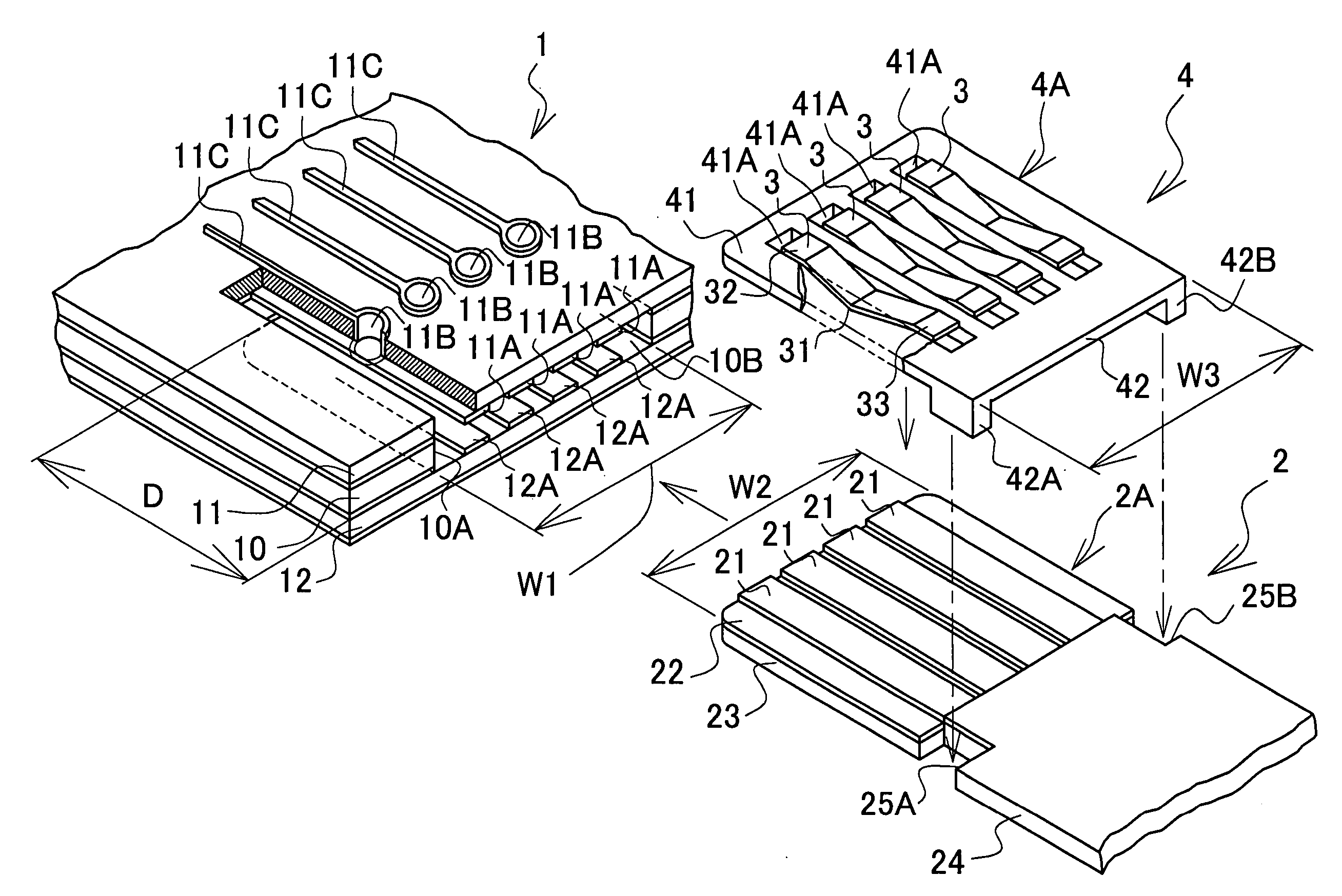
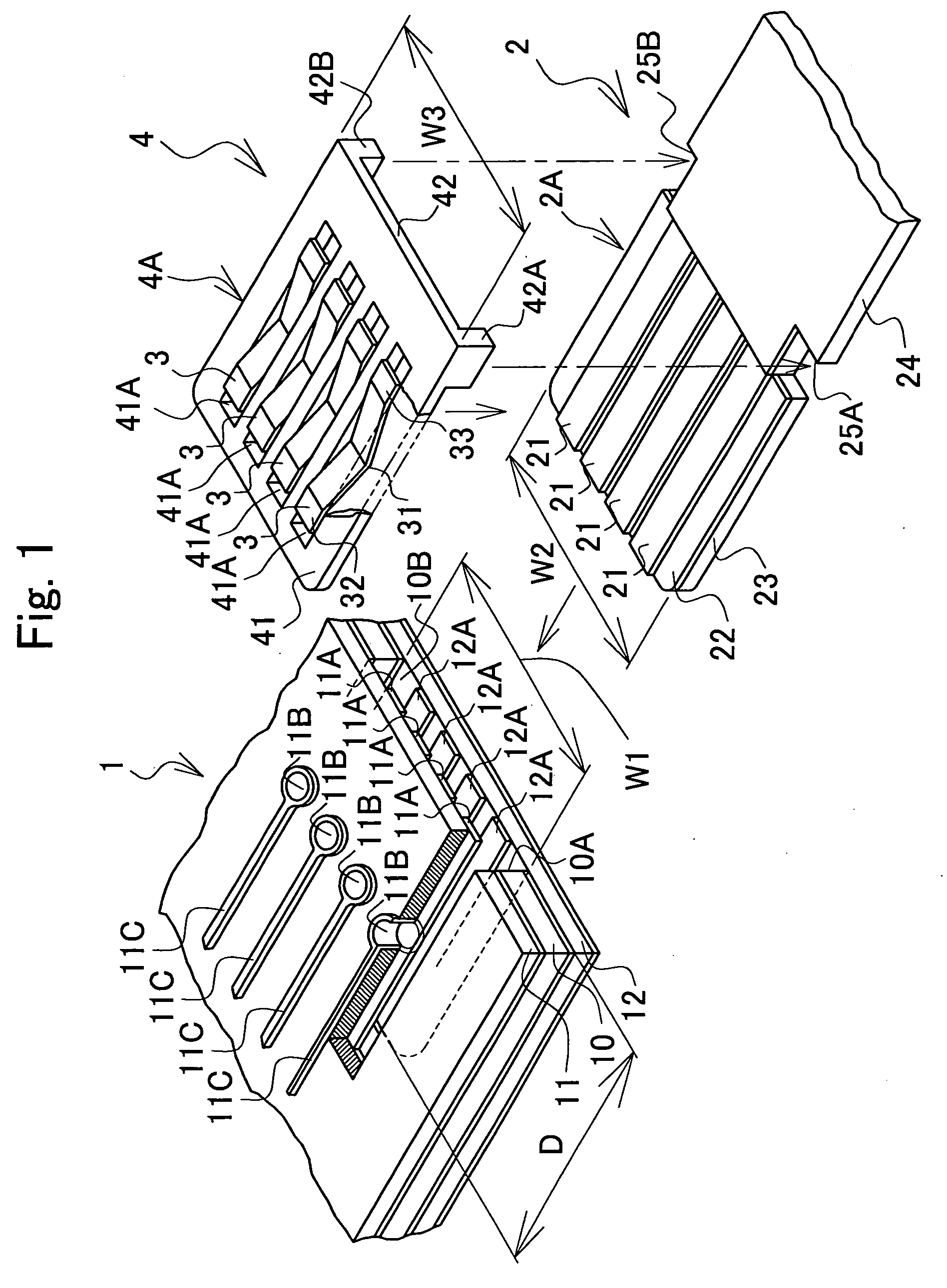
[0072]FIG. 1 is a perspective view showing a FPC and a printed wiring board according to a first embodiment of the present invention.

[0073] The FPC 2 includes an elongated substrate 22, a reinforcing plate 23 bonded to the lower surface of the substrate 22, plural conductors 21 laminated on the upper surface of the substrate 22 and extending along an axial direction thereof.

[0074] The FPC 2 is coated with a polyimide film 24 with a top end portion exposed to form an exposed conductor 2A having a width W2. A pair of rectangular cut out portions 25A and 25B is formed at both ends in the width direction near a boundary between the exposed conductor 2A of the FPC 2 and the polyimide film 24.

[0075] The substrate 22 has an insulation property and is formed, for example, of a thin-film polyimide plate.

[0076] The conductor 21 is formed of a suitable material having conductivity and formability and is provided with nickel plating.

[0077] A slider 4 including plural elastic deformable fir...

second embodiment

[0101] This embodiment differs from the first embodiment in the configuration of a printed wiring board 9 and a FPC 5.

[0102]FIG. 5 is a perspective view showing the FPC 5 and the printed wiring board 9 according to the second embodiment of the present invention.

[0103] Inside of the insertion opening 10B of the printed wiring board 9, a relay connector 8 is attached The relay connector 8 has plural elastic deformable second contacts 6, a header 7 and a second housing 8A holding the plurality of the second contacts 6.

[0104] The second contact 6 has a main body 6A abutting on the top end portion of the FPC 5, a pair of arms 61 and 62 extending substantially parallel with each other in an insertion direction from the main body 6A to the FPC 5.

[0105] The arm 62 abuts on the line connecting terminal 11A.

[0106] The gap between one arm 61 and the other arm 62 is slightly smaller than the width of the FPC 5. When the top end portion of the FPC 5 is inserted into the second contact 6, th...


PUM


Abstract

The present invention relates to a connection structure for a printed wiring board to be electrically connected to a FPC. The FPC has an elongated substrate, and plural conductors are laminated on a surface of the substrate for extending along an axial direction of the substrate. The printed wiring board has an insertion opening provided at an edge surface for being inserted by a top end portion of the FPC, and plural line connecting terminals formed on an internal wall surface of the insertion opening. The top end portion of the FPC has a slider including plural elastic deformable first contacts, and a first housing for holding the plurality of contacts. The FPC is inserted into the insertion opening of the printed wiring board such that one end of the first contact presses the conductor and the other end of the first contact presses the line connecting terminal. The FPC can be connected to the printed wiring board on an edge surface thereof, allowing circuit elements to be mounted in high density, and improving freedom in designing wiring patterns.

Description

FIELD OF THE INVENTION [0001] The present invention relates to a connection structure for a printed wiring board. More particularly, the present invention relates to a connection structure for a printed wiring board for electrically connecting a FPC (Flexible Printed Circuit) and a printed wiring board formed by stacking plural plate members. RELATED ART [0002] Modules of electronic parts and printed wiring boards are mounted in electronic devices. Conventionally, FPCs, or Flexible Flat Cables have been used to connect these printed wiring boards and modules of electronic parts. [0003] Here, a printed wiring board comprises a base plate having an insulating substrate and a wiring pattern formed on this substrate, and circuit elements, such as ICs and connectors, which are connected to the wiring pattern on the base plate. ZIF (Zero Insertion Force)-type connectors which enable FPCs to be inserted and removed with little force are connectors used as circuit elements mounted on printe...

Claims


Application Information

Patent Timeline
IPC IPC(8): H01R12/24H05K1/14H05K3/36H05K3/46
CPCH01R12/79H05K2201/09163H05K3/365
Inventor UCHIDA, SHINJIYAMANE, HIROSHIFUNAKOSHI, AKIHITOMIURA, KAZUTO
Owner JST MFG CO LTD
Why Eureka
Try Eureka