Technique for reducing multipath interference in an FM receiver

a multipath interference and fm receiver technology, applied in the field of receivers, can solve the problems of long delay multipath, distortion in audio recovered from signals, and more expensive implementation so as to reduce the distortion of egc and mrc systems, reduce the cost of implementation, and minimize antenna switching

Active Publication Date: 2007-02-15
APTIV TECH LTD
View PDF12 Cites 12 Cited by
  • Summary
  • Abstract
  • Description
  • Claims
  • Application Information

AI Technical Summary

Benefits of technology

[0009] To prevent frequent searches that can result in audible switching noise, a threshold is introduced that desensitizes the fast distortion detector for a period following an antenna search. The threshold is decayed at a rate dependent on the overall RF signal level to provide a longer desensitized period for weak signals, which are more susceptible to disturbances. The slow distortion detector uses an averaging time that is a function of the received overall RF signal level, since, in weak signal conditions, the distortion being measured is more corrupted by noise. The averaging time may typically range between twenty-five microseconds for large signal levels to five hundred microseconds when the overall RF signal level is below a predetermined RF level. Antennas are ranked for trial selection based on their recently measured RF level. This approach helps to minimize antenna switching since an antenna having a larger signal level, which is more likely to be lower in distortion, is selected as the next trial antenna.

Problems solved by technology

As is well known, multipath interference is caused when two or more signal rays of an original transmitted signal converge upon a receiving antenna of a receiver at significantly different times. This misalignment or superposition of several delayed signals, which are replicas of the original signal, may cause distortion in audio recovered from the signals.
Typically, long delay multipath occurs in cities with large buildings and in mountainous regions.
However, EGC and MRC systems tend to be more expensive to implement, as they require multiple receiver analog front-ends.

Method used


Image

  • Technique for reducing multipath interference in an FM receiver
  • Technique for reducing multipath interference in an FM receiver
  • Technique for reducing multipath interference in an FM receiver

Examples


Embodiment Construction

[0022] Today, manufacturers of automotive radios have moved from analog receiver systems to receiver systems that have increasingly incorporated more digital components within the receiver systems. As a general rule, the functions that are performed by these digital components are being increasingly implemented in digital signal processing (DSP) software.

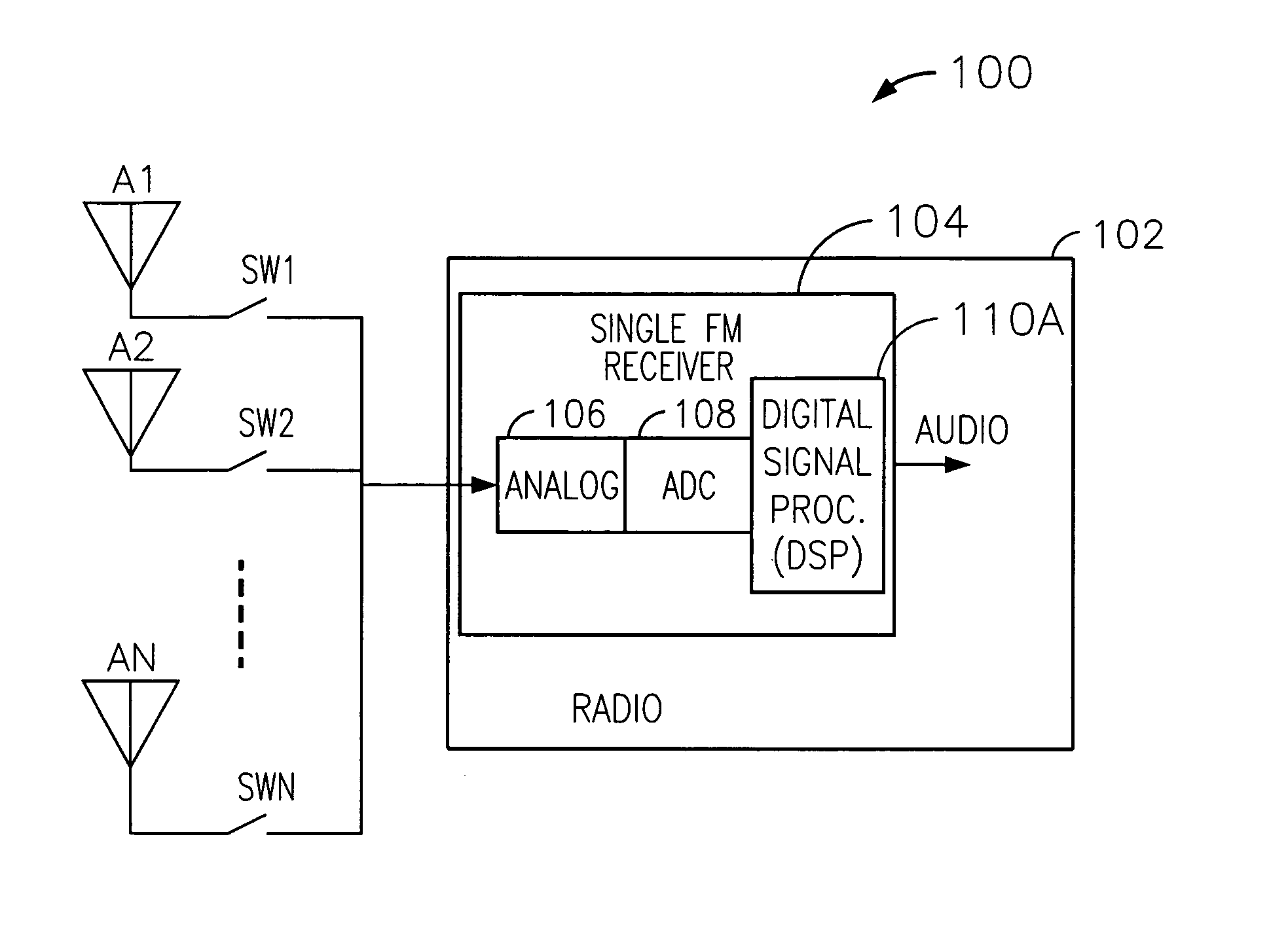
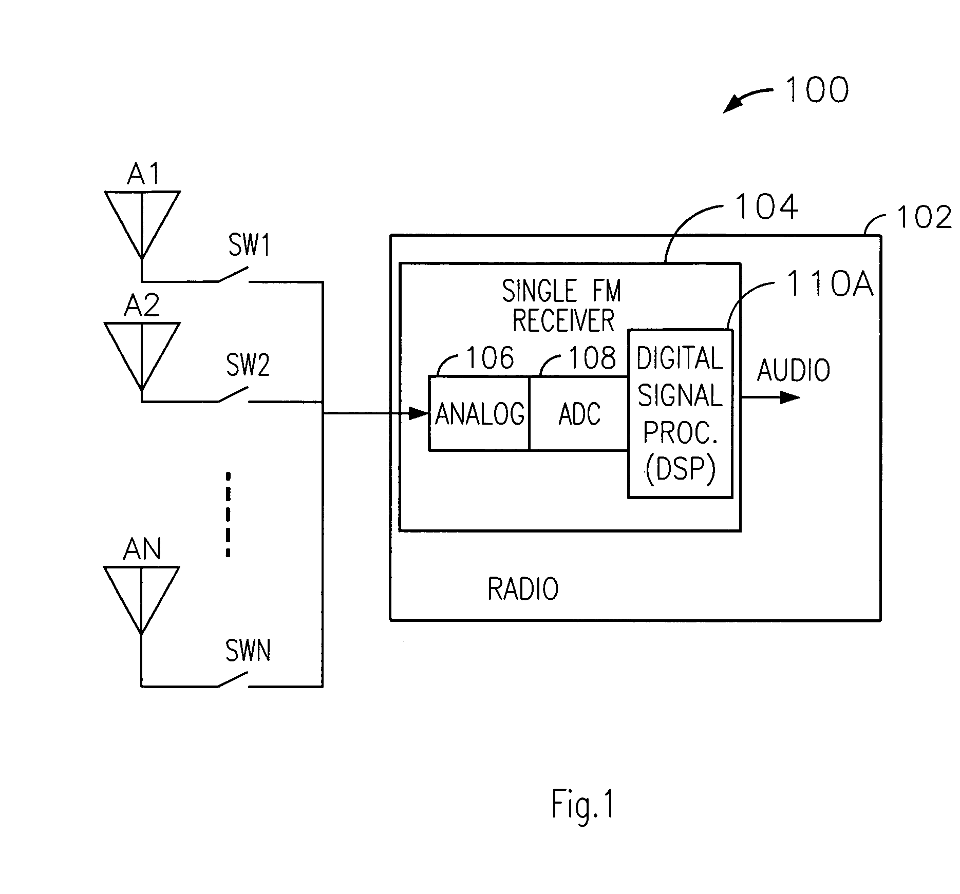
[0023] With reference to FIG. 1, an exemplary receiver system 100 is shown, which includes a plurality of antennas A1, A2 through AN, which are coupled to a single analog front-end 106 (of an FM receiver 104 incorporated within a radio 102) by a different one of a plurality of switches SW1, SW2 through SWN. The output of the front-end 106 is provided to an input of an analog-to-digital converter (ADC) 108, which converts the received analog signal to a digital signal. An output of the ADC 108 is coupled to an input of a digital signal processor (DSP) 110A, which digitally processes the digital signal to provide an audio signal.

[00...


PUM


Abstract

A technique for reducing multipath distortion in an FM receiver, with a plurality of switchable antennas, provides a fast distortion detector that monitors a received signal for significant distortion events of less than about 15 microseconds in duration. In response to a multipath event, the output of the fast distortion detector initiates a search for a lower distortion (better quality) antenna. To prevent frequent antenna searches from causing an audible disturbance, a threshold is introduced to desensitize the fast distortion detector. Threshold decay is a function of an overall received RF signal level. A slow distortion detector is also provided that measures distortions of the received signal relating to signal quality.

Description

TECHNICAL FIELD [0001] The present invention is generally directed to a receiver and, more specifically, to a technique for reducing multipath distortion in a mobile FM receiver having a single analog front-end. BACKGROUND OF THE INVENTION [0002] As is well known, multipath interference is caused when two or more signal rays of an original transmitted signal converge upon a receiving antenna of a receiver at significantly different times. This misalignment or superposition of several delayed signals, which are replicas of the original signal, may cause distortion in audio recovered from the signals. Distortion caused by the multipath interference may be attributable to long delay (e.g., greater than five microseconds between signals) multipath interference or short delay (e.g., less than five microseconds between signals) multipath interference. [0003] In a typical urban environment, RF signals experience changes in amplitude and phase due to short delay multipath. This amplitude an...

Claims


Application Information

Patent Timeline
Patent Type & Authority Applications(United States)
IPC IPC(8): H04B17/00H04B1/06
CPCH04B7/0802H04B17/345H04B17/20H04B7/0814
Inventor SHATARA, RAED S.BOYTIM, MATHEW A.LANGSTON, STEVEN S.
Owner APTIV TECH LTD
Why Eureka
Try Eureka