Tension/collar/reamer assemblies and methods

a technology of reamer and assembly, which is applied in the direction of drilling pipes, drilling holes/well accessories, cutting machines, etc., can solve the problems of buckling of the bottom hole assembly and the resulting the drill bit whirls, vibrates, and/or loses contact with the wellbore face in the desired drilling direction, etc., to achieve the effect of reducing the buckling of the bottom hole assembly and the tortuosity of the hol

Active Publication Date: 2007-02-22
STRATALOC TECH PROD +1
View PDF24 Cites 4 Cited by
  • Summary
  • Abstract
  • Description
  • Claims
  • Application Information

AI Technical Summary

Benefits of technology

[0004] Accordingly, it is an objective of the present invention to provide an improved drilling assembly and method.
[0005] An objective of another possible embodiment is to provide faster drilling ROP (rate of penetration), longer bit life, reduced stress on drill string joints, truer gage borehole, improved circulation, improved cementing, improved lower noise MWD and LWD, improved wireline logging accuracy, improved screen assembly running and installation, fewer bit trips, reduced or elimination of tortuosity, reduced or elimination of drill string buckling, reduced hole washout, improved safety, and / or other benefits.
[0007] An objective of yet another possible embodiment of the present invention provides a much shorter compression length of the bottom hole assembly with respect to the first order of buckling length to thereby virtually eliminate buckling of the bottom hole assembly and the resulting tortuosity in the hole.
[0008] Another objective of yet another possible embodiment of the present invention is to provide an outer steel sleeve for the bottom hole assembly which is held in tension instead of being in compression even at close distances from the drill bit such that buckling of the drill string is eliminated.
[0009] Another objective of yet another possible embodiment of the present invention is to apply an increased amount of weight adjacent the bit and to permit increased revolutions per minute (RPM) of the drill string to thereby increase the drilling rate of penetration (ROP) in many formations.

Problems solved by technology

Due to their size and construction, prior art heavy weight drill collars are unbalanced to some degree and tend to introduce variations.
Moreover, even if they were perfectly balanced, the heavy weight drill collars have a buckling point and tend to bend up to this point during the drilling process.
The result of imbalanced heavy weight collars and the bending of the overall downhole assembly produces a flywheel effect with an imbalance therein that may easily cause the drill bit to whirl, vibrate, and / or lose contact with the wellbore face in the desired drilling direction.

Method used


Image

  • Tension/collar/reamer assemblies and methods
  • Tension/collar/reamer assemblies and methods
  • Tension/collar/reamer assemblies and methods

Examples


Embodiment Construction

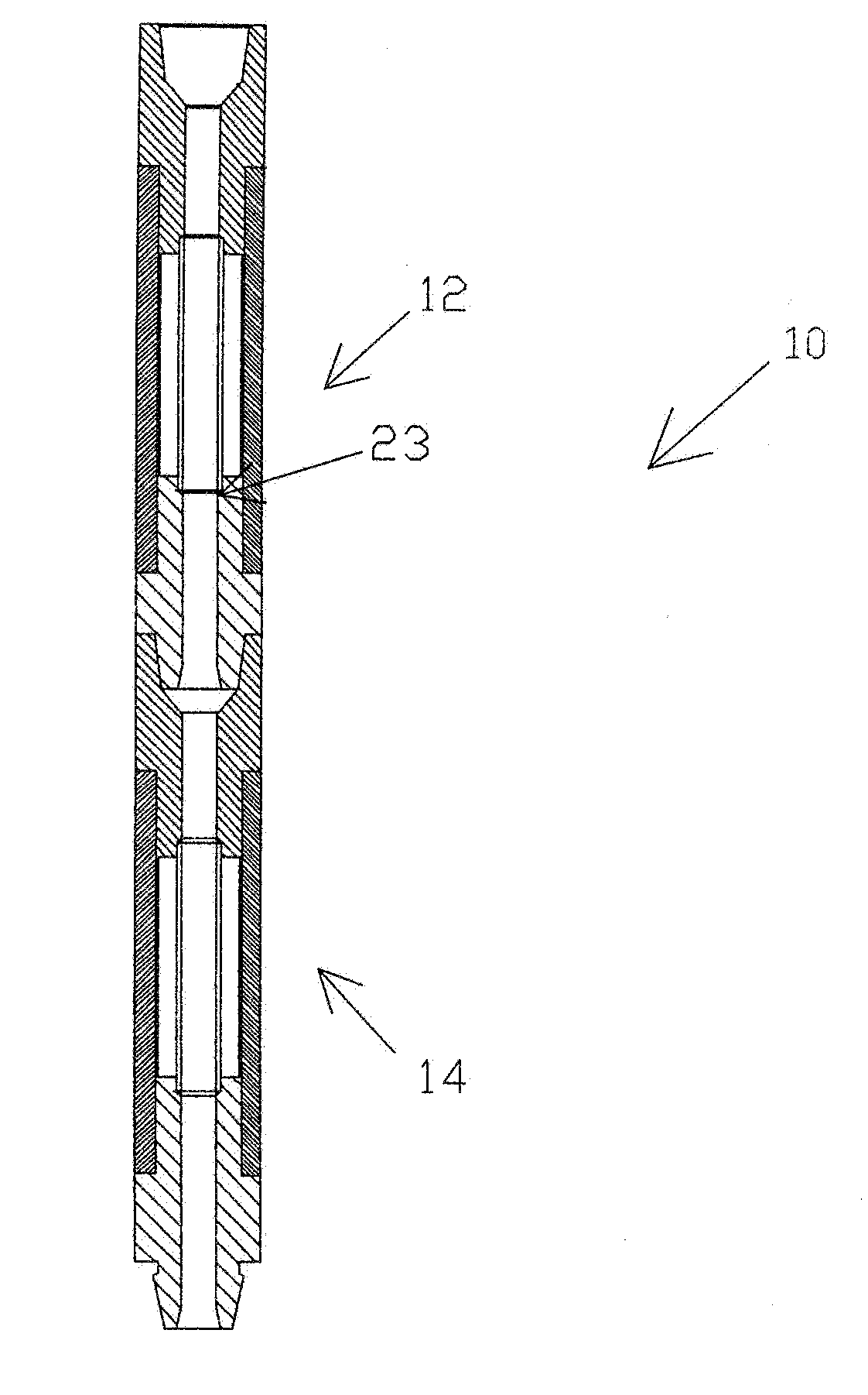
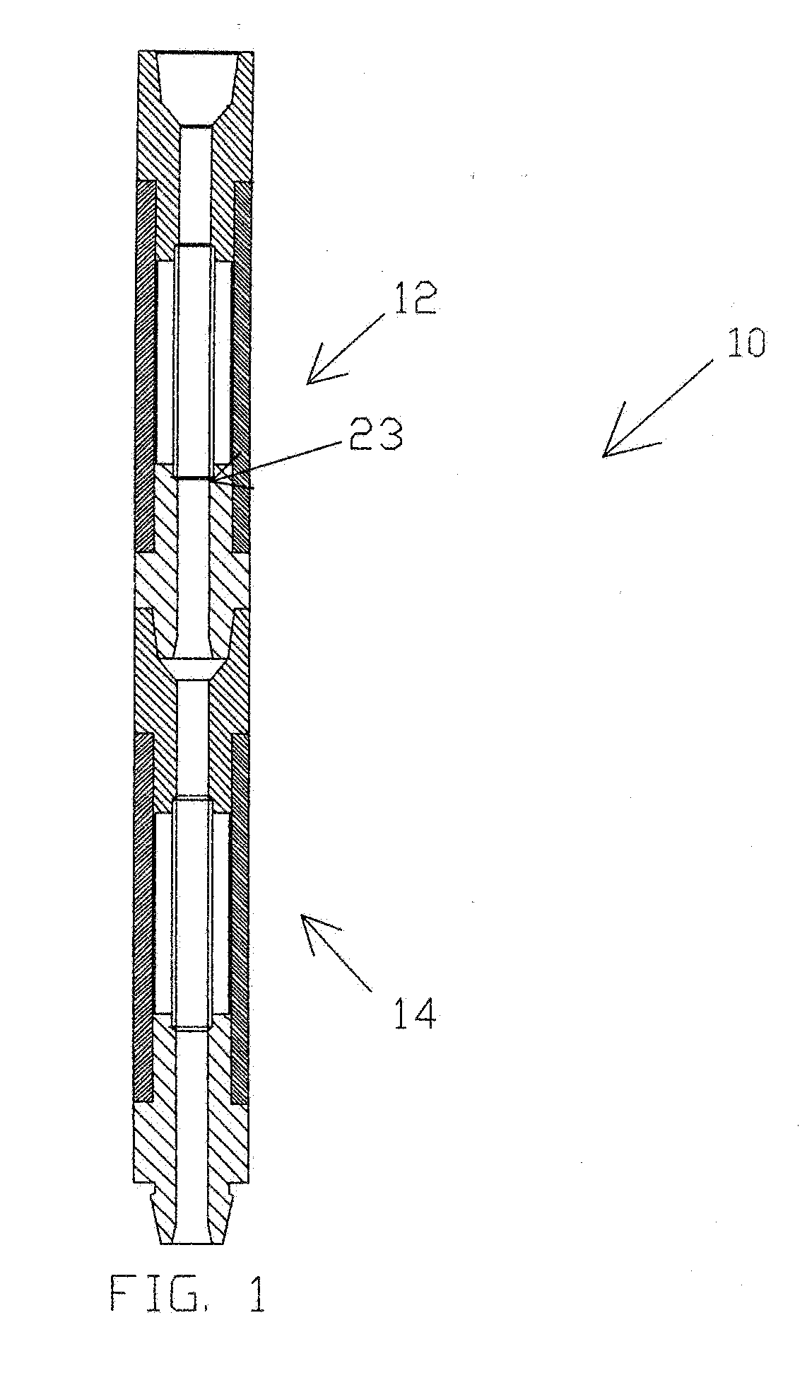
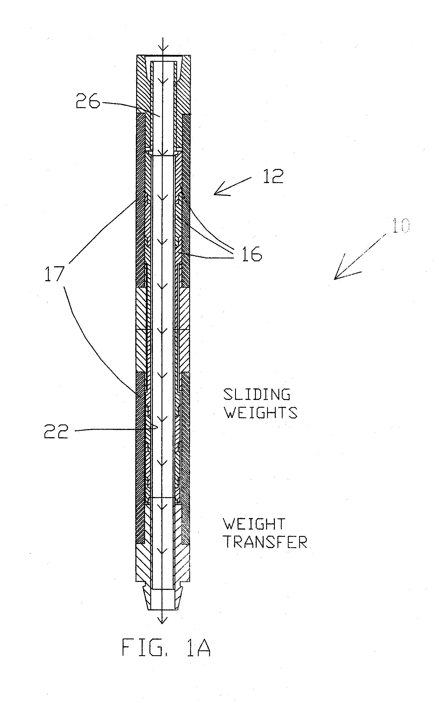
[0055] Now referring to the drawings, and more particularly to FIG. 1, FIG. 1A, and FIG. 1B, there is shown an elevational view of one possible construction of a portion of a drilling assembly 10 which may be utilized in a drill string in accord with the present invention. Drilling assembly 10 may preferably be utilized as a portion of a bottom hole drilling assembly but may also be used elsewhere in the drill string as desired. In FIG. 1, upper section 12 and lower section 14 may be the same or may be significantly different in construction. Upper section 12 is connected to lower section 14 through sub 23. FIG. 1A shows one possible construction for upper heavy weight assembly 12 and FIG. 1B shows a possible construction for lower heavyweight assembly section 14. In the particular embodiments shown in FIG. 1A and FIG. 1B, upper assembly portion 12 and lower assembly portion 14 function differently as discussed hereinafter and may be utilized separately or in conjunction with each o...


PUM


Abstract

The present invention provides drilling assembles and methods that are especially useful for a bottom hole drilling assembly for drilling / reaming / or other operations related to drilling a borehole through an earth formation. In one embodiment, the drilling assembly utilizes standard drill collars which are modified to accept force transfer sections. In another embodiment, the drilling assembly comprises a tension inducing sub which creates a force that may be used to place the bottom hole assembly or portions thereof in tension. In another embodiment, a reaming assembly is held in tension to provide a stiffer reaming assembly.

Description

[0001] The benefit of U.S. Provisional Patent Application No. 60 / 442,737, filed Jan. 27, 2003, and U.S. Utility patent application Ser. No. 10 / 761,892, filed Jan. 21, 2004, and U.S. Provisional Patent Application No. 60 / 721,406, filed Sep. 28, 2005, is hereby claimed, and is hereby incorporated by reference.TECHNICAL FIELD [0002] The present invention relates generally to drilling wellbores for oil, gas, and the like. More particularly, the present invention relates to assemblies and methods for improved drill bit and drill string performance. BACKGROUND ART [0003] Due to their size and construction, prior art heavy weight drill collars are unbalanced to some degree and tend to introduce variations. Moreover, even if they were perfectly balanced, the heavy weight drill collars have a buckling point and tend to bend up to this point during the drilling process. The result of imbalanced heavy weight collars and the bending of the overall downhole assembly produces a flywheel effect wi...

Claims


Application Information

Patent Timeline
Patent Type & Authority Applications(United States)
IPC IPC(8): E21B17/00E21B7/00E21B17/02E21B17/16
CPCE21B7/28E21B17/16E21B17/02E21B17/00
Inventor NICHOLS, RICHARD A.TAYLOR, BRUCE L.PIERCE, ROGER
Owner STRATALOC TECH PROD
Why Eureka
Try Eureka