Rotary sprinkler with reduced wear

a technology of rotary sprinklers and sprinklers, which is applied in the direction of rotary bearings, shafts and bearings, bearings, etc., can solve the problems of high rotational speed

Inactive Publication Date: 2007-02-22
NETAFIM LTD
View PDF8 Cites 24 Cited by
  • Summary
  • Abstract
  • Description
  • Claims
  • Application Information

AI Technical Summary

Benefits of technology

[0015] Enlarging the diameter of the rotor axle tip prevents the penetration of contaminating particles into the contact zone of the tip and the socket both in the upper (operative) position of the rotor with the tip abutting the bottom and in the lower position with the tip aligned with the in...

Problems solved by technology

Dynamic rotary sprinklers are characterized by high rot...

Method used


Image

  • Rotary sprinkler with reduced wear
  • Rotary sprinkler with reduced wear
  • Rotary sprinkler with reduced wear

Examples


Embodiment Construction

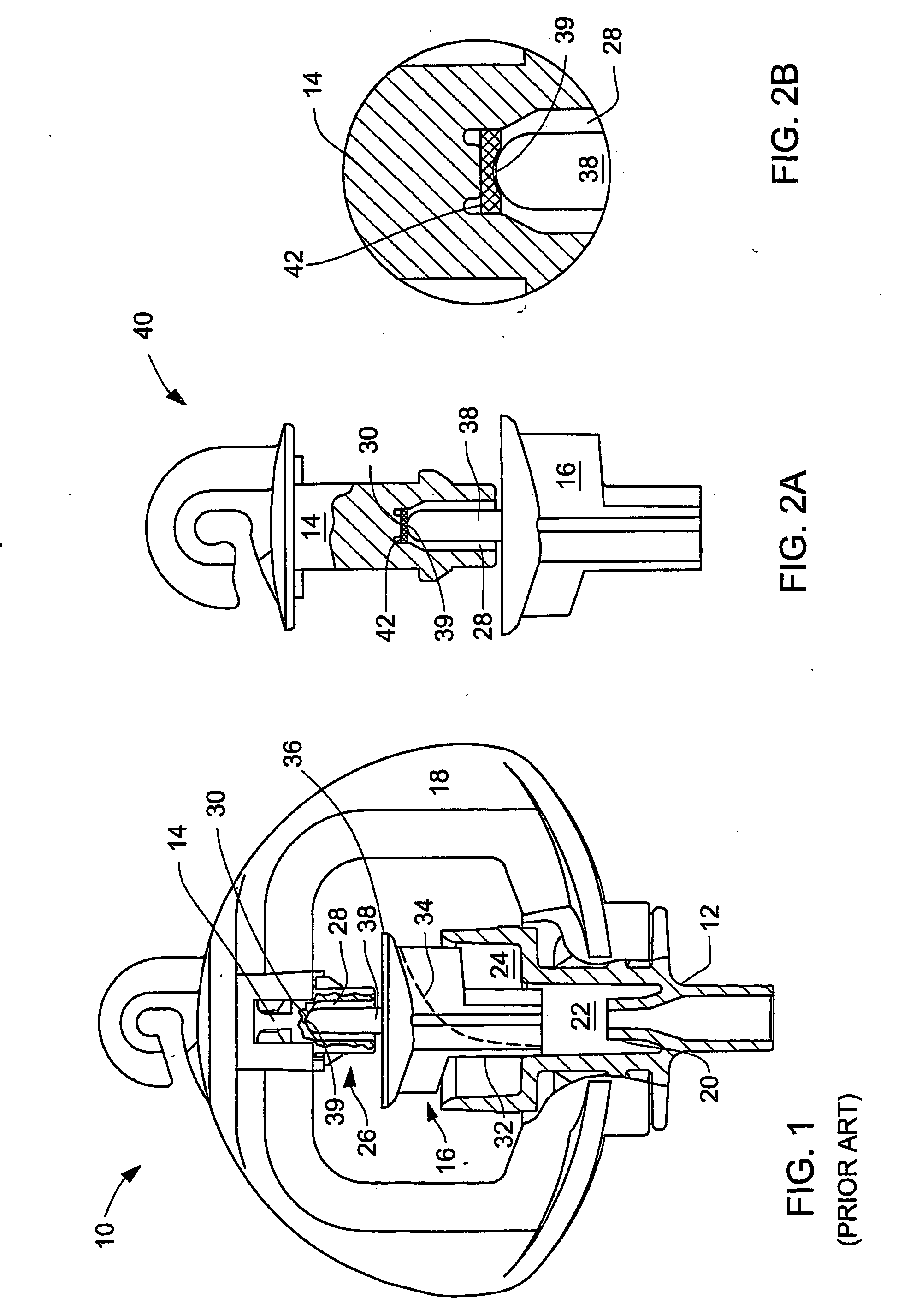
[0025] A typical dynamic rotary sprinkler known in the prior art was described above with reference to FIG. 1. A rotor-bearing assembly 40 of a similar rotary sprinkler in accordance with one embodiment of the present invention, is shown in FIG. 2A, without the sprinkler base and the connecting bridge, which are generally the same as in FIG. 1.

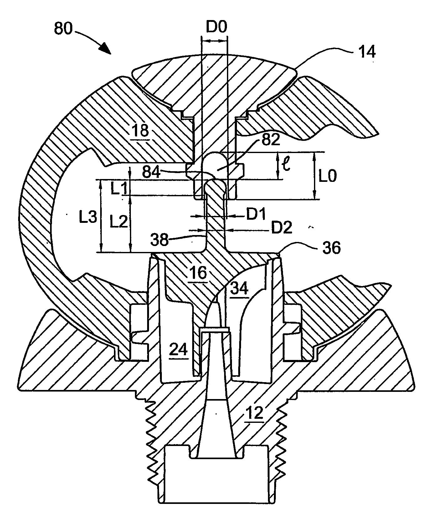
[0026] As shown in FIG. 2, the rotor-bearing assembly comprises the thrust bearing 14 and the rotor 16, both made of plastic material. The rotor 16 has an axle 38 with a tip 39, while the thrust bearing 14 has an axial socket 26 comprising a bore 28 and a bottom 30.

[0027] Furthermore, the bearing 14 is equipped with a wear-resistant insert 42 made of material which is much harder than the plastic material of the rotor and the bearing. The insert is a flat polished disc which is corrosion-proof in the field, i.e. in water solution of fertilizers and other chemicals. The disc may be made of industrial sapphire stone, industrial ruby stone, sta...


PUM


Abstract

A rotary sprinkler comprising a rotor (16) with an axle (38) having a tip, and a thrust hearing (14) with a socket (26) having a bottom (30), the socket being adapted to receive for rotation the axle so that the tip abuts the bottom in a contact zone. The sprinkler further comprises a hard element (42) constituting a part of the bottom or of the tip. The hard element (42) is made of harder material than the axle or the socket, thereby reducing their wear.

Description

FIELD OF THE INVENTION [0001] This invention relates to rotary sprinklers, in particular to dynamic sprinklers with unlimited speed of rotation where an operating rotor is supported in a thrust bearing. BACKGROUND OF THE INVENTION [0002] Dynamic rotary sprinklers are characterized by high rotational speed, which is due to the lack of braking mechanism. Their advantages lie in the simple construction that accounts for their low price. Their shortcomings are relatively small range (radius) of irrigation and small water droplets emitted as a result of the high speed of rotation. [0003] A typical dynamic rotary sprinkler known in the art is shown in FIG. 1. The sprinkler 10 is made of plastic parts: a sprinkler base 12 mountable to irrigation water pipe (not shown), a thrust bearing 14, a rotor (swivel) 16, and a connecting bridge 18. The base 12 has an axial inlet nozzle 20, a coaxial intermediate bore 22 and a coaxial exit chamber 24. The thrust bearing 14 has an axial socket 26 compr...

Claims


Application Information

Patent Timeline
IPC IPC(8): B05B3/04F16C17/08
CPCF16C17/08B05B3/0486
Inventor COHEN, BOAZ
Owner NETAFIM LTD
Why Eureka
Try Eureka