Bumper for a motor vehicle

a bumper and motor vehicle technology, applied in the direction of bumpers, vehicle safety arrangments, transportation and packaging, etc., can solve the problems of undesired increase in overall weight, and achieve the effects of reducing weight, material saving, and reducing weigh

Inactive Publication Date: 2007-02-22
BENTELER AUTOMOBILTECHNIK GMBH
View PDF8 Cites 38 Cited by
  • Summary
  • Abstract
  • Description
  • Claims
  • Application Information

AI Technical Summary

Benefits of technology

[0015] According to another feature of the present invention, the web of the inner shell member may be formed in an area of the end portions with an opening which extends to the transition zone and has a rounded configuration in an area proximal to the central length portion so that the end portion is forked to define an upper arm and a lower arm. The opening may be sized large enough to clear almost the entire end surface of the crash boxes. This allows attachment of a towing apparatus in the area of the crash boxes and in addition results in material saving and weight reduction. For reasons of stability, it may be suitable to interconnect the ends of the upper and lower arms by a vertical link.
[0016] In correspondence to the waisted configuration of the inner shell member, it is also possible to construct the outer shell member with a midsection which extends between the crash boxes and has a height which is smaller than a height in an area of the crash boxes. This, too, results in material saving and weight reduction.
[0017] According to another feature of the present invention, the inner shell member has a length dimension which may be shorter than a length dimension of the outer shell member. The shorter overall length of the inner shell member is possible because it absorbs only tensile stress so that there is no need to extend the inner shell member laterally beyond the crash boxes.
[0018] According to another feature of the present invention, the outer shell member has attachment zones which embrace the end portions of the inner shell member so that the inner and outer shell members can be connected to the crash boxes by common fastening bolts. This reduces assembly and disassembly of the bumper.
[0019] In general, it is sufficient for the inner and outer shell members to touch one another only in an area of the crash boxes. In the area of the crash boxes, the attachment zone of the outer shell member may be pressed against the arms in the end portion of the inner shell member so that the inner shell member is clamped between the outer shell member and the crash box, when the bumper is assembled. Further direct contact surfaces between the inner and outer shell members are not required. In certain cases, it may be suitable to provide at least one support member for prop up of the outer shell member in its midsection in relation to the inner shell member. This indirect contact between the shell members contributes to an overall stiffening of the bumper. The support member may be designed, for example, in the form of a metal sheet that bridges the distance between the inner and outer shell members.

Problems solved by technology

Conventional bumpers suffer shortcomings because in order to meet the standards of older or current crash repair tests, their overall weight has increased in an undesired manner.

Method used


Image

  • Bumper for a motor vehicle
  • Bumper for a motor vehicle
  • Bumper for a motor vehicle

Examples


Embodiment Construction

[0026] Throughout all the Figures, same or corresponding elements are generally indicated by same reference numerals. These depicted embodiments are to be understood as illustrative of the invention and not as limiting in any way. It should also be understood that the drawings are not necessarily to scale and that the embodiments are sometimes illustrated by graphic symbols, phantom lines, diagrammatic representations and fragmentary views. In certain instances, details which are not necessary for an understanding of the present invention or which render other details difficult to perceive may have been omitted.

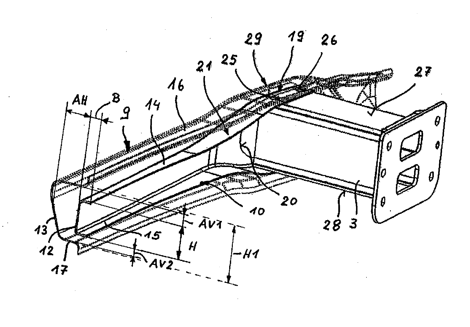
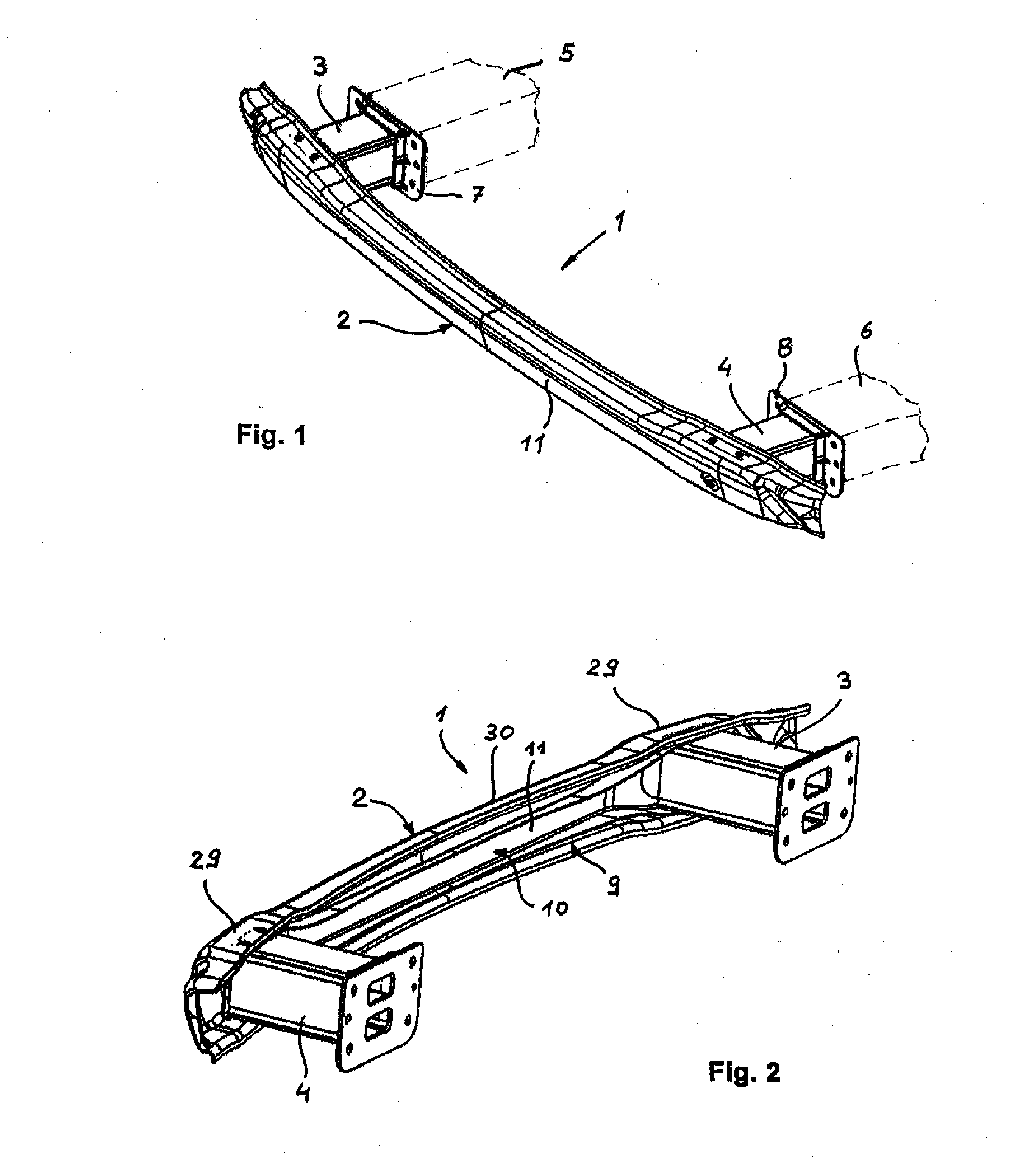
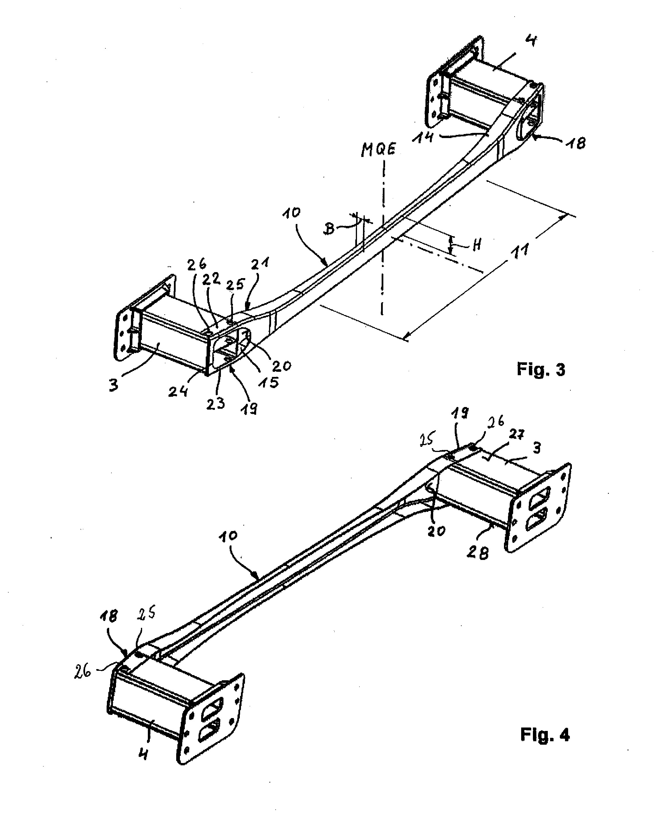
[0027] Turning now to the drawing, and in particular to FIG. 1, there is shown a top, front and side perspective view of a bumper according to the present invention, generally designated by reference numeral 1, for a motor vehicle. The bumper 1 includes a cross member 2 which is mounted via crash boxes 3, 4 to side rails 5, 6 of the vehicle frame. As shown in particular in F...


PUM


Abstract

A bumper for a motor vehicle includes a cross member which is disposed transversely to side rails of a motor vehicle frame and connected to the side rails via crash boxes. The cross member has a C-shaped cross section and includes an outer shell member and an inner shell member. The inner shell member is constructed as tension link which is made of a material having a tensile strength that is greater than the tensile strength of a material of the outer shell member.

Description

CROSS-REFERENCES TO RELATED APPLICATIONS [0001] This application claims the priority of German Patent Application, Serial No. 10 2005 039 489.2, filed Aug. 18, 2005, pursuant to 35 U.S.C. 119(a)-(d), the content of which is incorporated herein by reference. BACKGROUND OF THE INVENTION [0002] The present invention relates to a bumper for a motor vehicle. [0003] Nothing in the following discussion of the state of the art is to be construed as an admission of prior art. [0004] Bumpers for motor vehicles are constructed to prevent damage to the vehicle body structure in the event of a crash or impact at low speed (up to 16 km / h) and directly affect the type of damage to a vehicle and the damage assessment. As a result, the construction of bumpers is used for categorizing vehicles in certain insurance classes. The lower the expected repair costs in the event of a collision, the better the insurance classification. [0005] Bumpers are typically arranged across the front and rear of a motor...

Claims


Application Information

Patent Timeline
Patent Type & Authority Applications(United States)
IPC IPC(8): B60R19/02
CPCB60R19/18B60R19/34B60R2019/1826
Inventor LUTKE-BEXTEN, ULRICHROLL, MICHAELMOLLEMEIER, ELMAR
Owner BENTELER AUTOMOBILTECHNIK GMBH
Why Eureka
Try Eureka