Optical receptacle

Active Publication Date: 2007-02-22
NIPPON ELECTRIC GLASS CO LTD
View PDF5 Cites 9 Cited by
  • Summary
  • Abstract
  • Description
  • Claims
  • Application Information

AI Technical Summary

Benefits of technology

[0041] Further, a construction in which the adhesive contains 10 vol % or more of fillers having a maximum particle size of 0.5 μm or less and an average particle size of 0.3 μm or less is employed, to thereby form easily and uniformly an adhesive layer between the precision sleeve and the stub with an optical fiber in a circumferential direction and hold stably and more easily the stub with an optical fiber at the center of the precision sleeve.
[0042] The stub with an optical fiber is self-aligned and bonded and fixed in the inner hole of the precision sleeve having desired rigidity, to thereby arrang

Problems solved by technology

However, the split sleeve 2 only holds and does not fix the stub 4 with an optical fiber.
Thus, the conventional optical receptacle has a problem of difficulties in cost reduction.
As a result, the optical receptacle

Method used


Image

  • Optical receptacle
  • Optical receptacle
  • Optical receptacle

Examples


example 1

[0052] A stub with an optical fiber and a precision sleeve were each formed from crystallized glass having a composition shown in Table 1 below.

TABLE 1Sample No.12345GlassSiO257.866.367.464.365.9compositionAl2O324.618.216.618.018.2(Mass %)Li2O2.72.32.32.52.0K2O7.03.43.55.03.4TiO22.81.83.03.01.5ZrO23.21.81.82.01.8ZnO1.03.12.03.13.6MgO—1.01.01.01.5CaO———0.40.6BaO———0.51.4B2O3——2.0——Na2O0.4————P2O5——0.4——As2O30.5——0.20.1Bi2O3—2.1———Crystallizationconditions (° C.)Nucleation780780790780780temperatureCrystal growth1000100098010501000temperatureMain crystalsβ-Quartzβ-Spodumeneβ-Spodumeneβ-Spodumeneβ-Spodumenesolidsolidsolidsolidsolidsolutionsolutionsolutionsolutionsolution

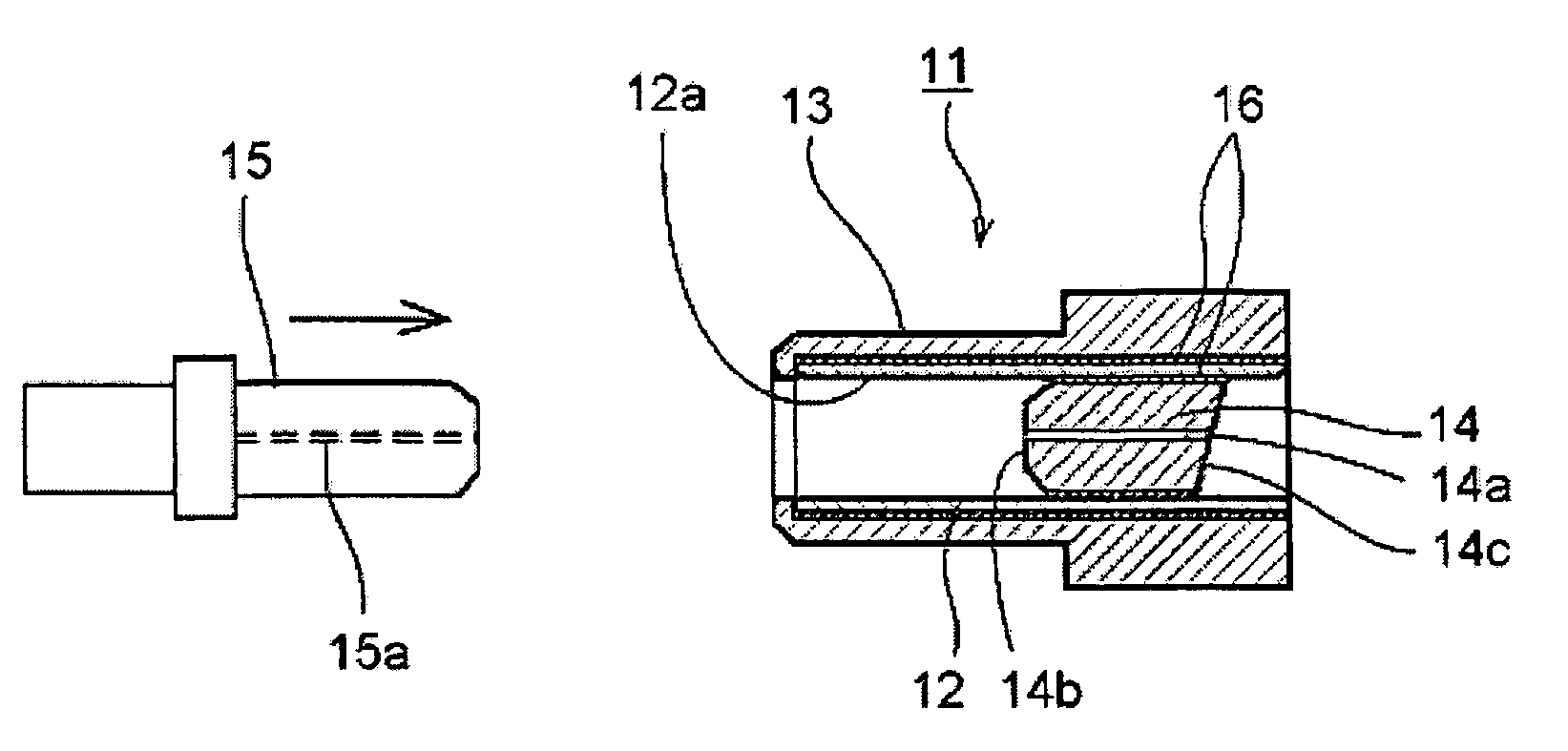
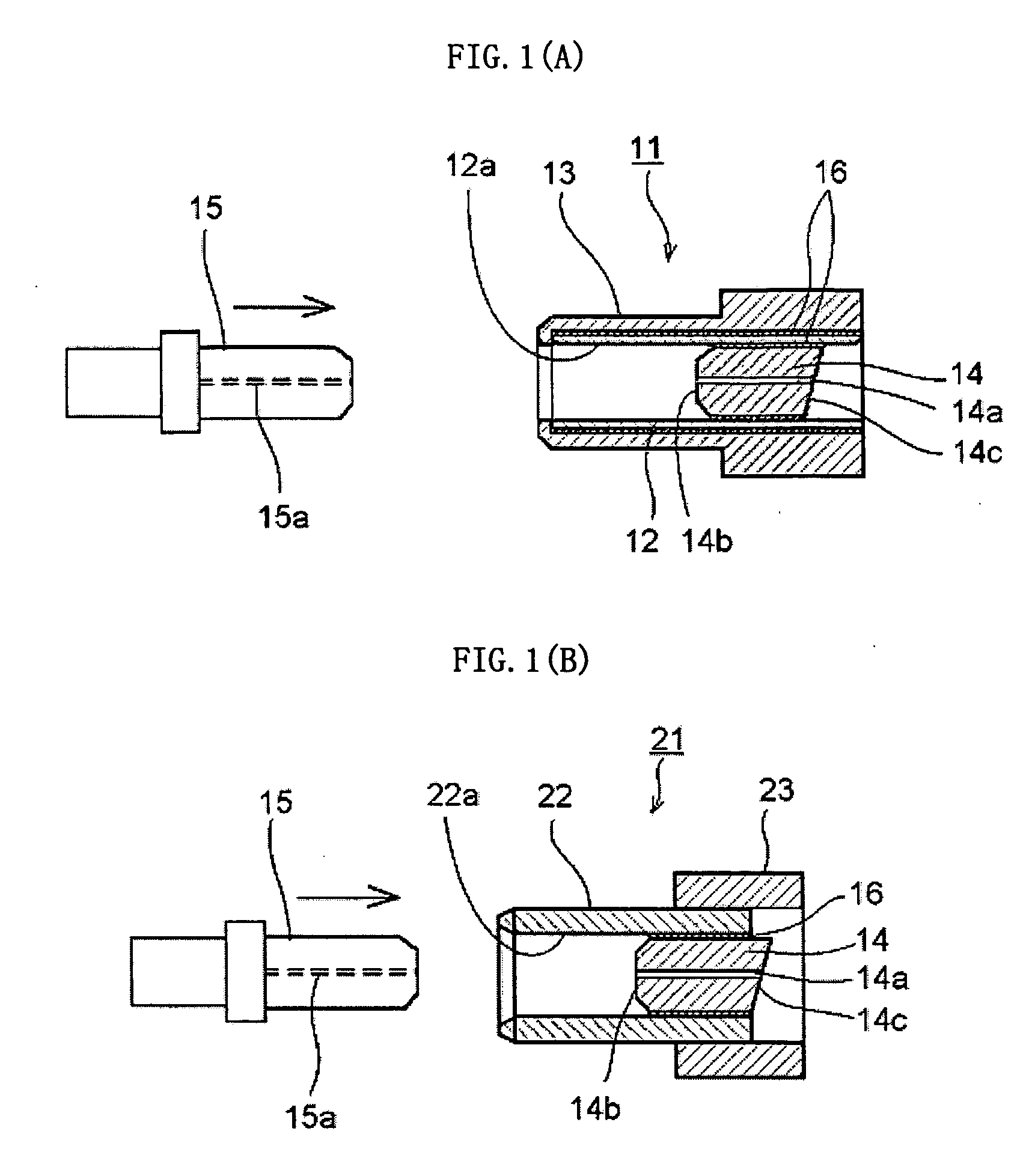
[0053] As shown in FIG. 1(A), the optical receptacle 11 of Example 1 included: the precision sleeve 12 formed of crystallized glass and having an inner hole with a larger inner diameter by 0 to 1.5 μm than an outer diameter of the optical connector ferrule 15; and the stub 14 with an optical fiber inserted into one end...

example 2

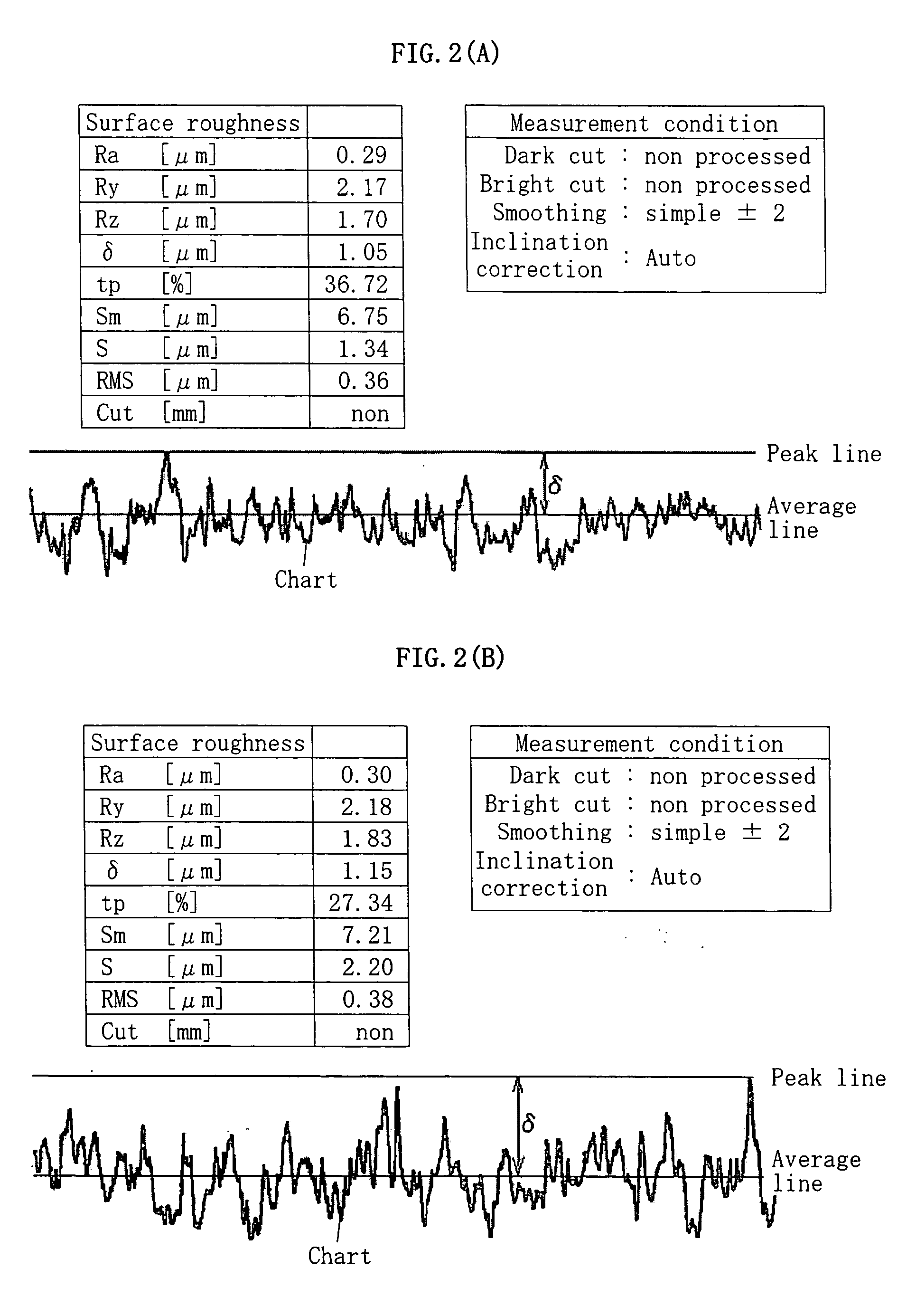
[0059] The precision sleeve 12 formed of crystallized glass having the inner hole 12a with a surface roughness Ra value of 0.3 μm, an outer diameter of 1.80 mm, and an inner diameter of 1.2495+0.0005 / −0 mm was produced. Further, the optical fiber 14a was inserted and bonded to the capillary 14b formed of crystallized glass having the inner hole and outer periphery with a surface roughness Ra value of 0.3 μm, an outer diameter of 1.2490+ / −0.0005 mm, and a concentricity of 0.5 μm, to thereby produce the stub 14 with an optical fiber. The stub 14 with an optical fiber was fixed to the inner hole 12a of the precision sleeve 12 through the epoxy-based adhesive 16, and the precision sleeve 12 was fixed to the inner hole of the sleeve holder 13 through the epoxy-based adhesive 16, to thereby produce the optical receptacle 11. Ten samples of optical receptacles 11 were produced. The optical connector ferrule 15 was inserted into the inner hole 12a of the precision sleeve 12 of each optical ...

example 3

[0065] The precision sleeve 12 formed of borosilicate glass having an outer diameter of 1.80 mm and an inner diameter of 1.2495+0.001 / −0 mm was produced. Further, the optical fiber 14a was inserted and bonded to the capillary 14b formed of crystallized glass having the inner hole and outer periphery with a surface roughness Ra value of 0.3 μm, an outer diameter of 1.2490+ / −0.0005 mm, and a concentricity of 0.5 μm, to thereby produce the stub 14 with an optical fiber. The stub 14 with an optical fiber was fixed to the inner hole 12a of the precision sleeve 12 through the epoxy-based adhesive 16, and the precision sleeve 12 was fixed to the inner hole of the sleeve holder 13 through the epoxy-based adhesive 16, to thereby produce the optical receptacle 11. Ten samples of optical receptacles 11 were produced. The optical connector ferrule 15 was inserted into the inner hole 12a of the precision sleeve 12 of each optical receptacle 11 thus produced so as to oppose the stub 14 with an op...


PUM


Abstract

An optical receptacle comprises a precision sleeve, a stub with an optical fiber fixed to one end of an inner hole of the precision sleeve through an adhesive, and a sleeve holder fixed to an outer periphery of the precision sleeve by press-fitting or through the adhesive. An outer periphery of the stub with an optical fiber and/or the inner hole of the precision sleeve has a surface roughness Ra value of 0.1 μm or more and 0.5 μm or less.

Description

TECHNICAL FIELD [0001] The present invention relates to an optical receptacle used for optically connecting a signal between an optical fiber connector and an optical receiver / optical transmitter. BACKGROUND ART [0002] A conventional receptacle 1 as shown in FIG. 3(A) employs a split sleeve 2. In this optical receptacle 1, a stub 4 with an optical fiber is fixed to a stub holder 3 by press-fitting or through an adhesive. The stub 4 with an optical fiber is held in the split sleeve 2 having sufficient elasticity, and the split sleeve 2 is closed within a clamping allowance to hold the stub 4 with an optical fiber. [0003] An optical connector ferrule 7 is inserted from an opening part 5a of a split sleeve cap 5 of the optical receptacle 1, and the optical connector ferrule 7 and the stub 4 with an optical fiber are aligned precisely and concentrically by the split sleeve 2. An optical receiver / optical transmitter 6 provided with a photosemiconductor 6a, a lens 6b, and a holder 6c for ...

Claims


Application Information

Patent Timeline
IPC IPC(8): G02B6/36G02B6/38G02B6/42
CPCG02B6/3874G02B6/3875G02B6/421
Inventor WADA, MASANORITAKEUTI, HIROKAZU
Owner NIPPON ELECTRIC GLASS CO LTD
Why Eureka
Try Eureka