Two members cerclage tool

a cerclage tool and two-member technology, applied in the field of cerclage tools, can solve the problems of insufficient strength of the device to go through the bone surrounding, complicated anatomical structures, and difficult surgical procedures on and in the vicinity of a bone with closely neighboring nerves, etc., and achieve the effect of simple and effectiv

Active Publication Date: 2007-02-22
SYNTHES GMBH
View PDF15 Cites 18 Cited by
  • Summary
  • Abstract
  • Description
  • Claims
  • Application Information

AI Technical Summary

Benefits of technology

[0017] Accordingly, it is an object of the present invention to provide a simple and effective tool and method to pass the wire or cable around

Problems solved by technology

Surgical procedures on and in the vicinity of a bone with closely neighboring nerves, arteries, muscle, ligaments, complicated anatomical structures, and delicate areas represent a difficult and time consuming task for the surgeon.
The difficulty is to perform such procedures accurately, minimizing stress, trauma, risk, and injury to a patient, and with little difficulty for a surgeon performing such procedures, in as rapid a time frame as possible.
However, none of the tools adequately satisfies these aforementioned needs.
For example, U.S. Pat. No. 4,606,335, U.S. Pat. No. 5,772,663 and U.S. Pat. No. 5,501,688 have the problem of requiring

Method used


Image

  • Two members cerclage tool
  • Two members cerclage tool
  • Two members cerclage tool

Examples


Embodiment Construction

[0030] Hereinafter, a method of cerclage wiring according to the preferred embodiment of the present invention will be explained with reference to FIGS. 1-6.

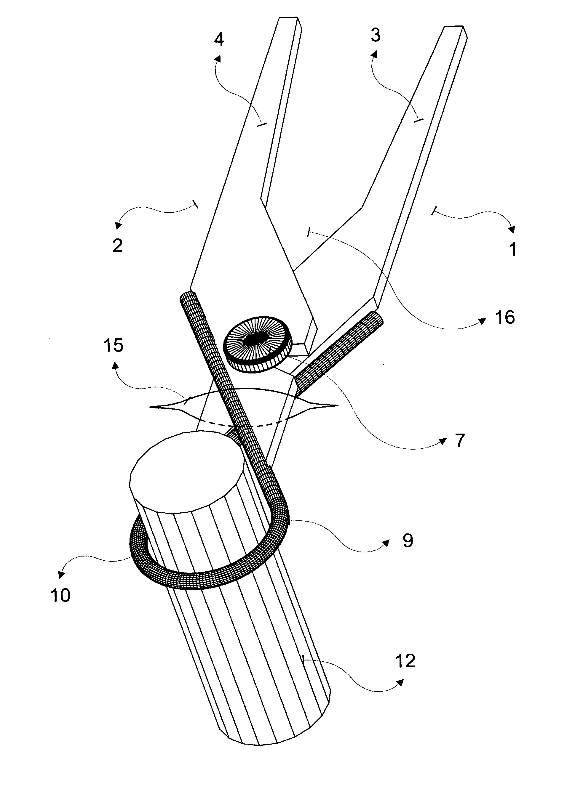
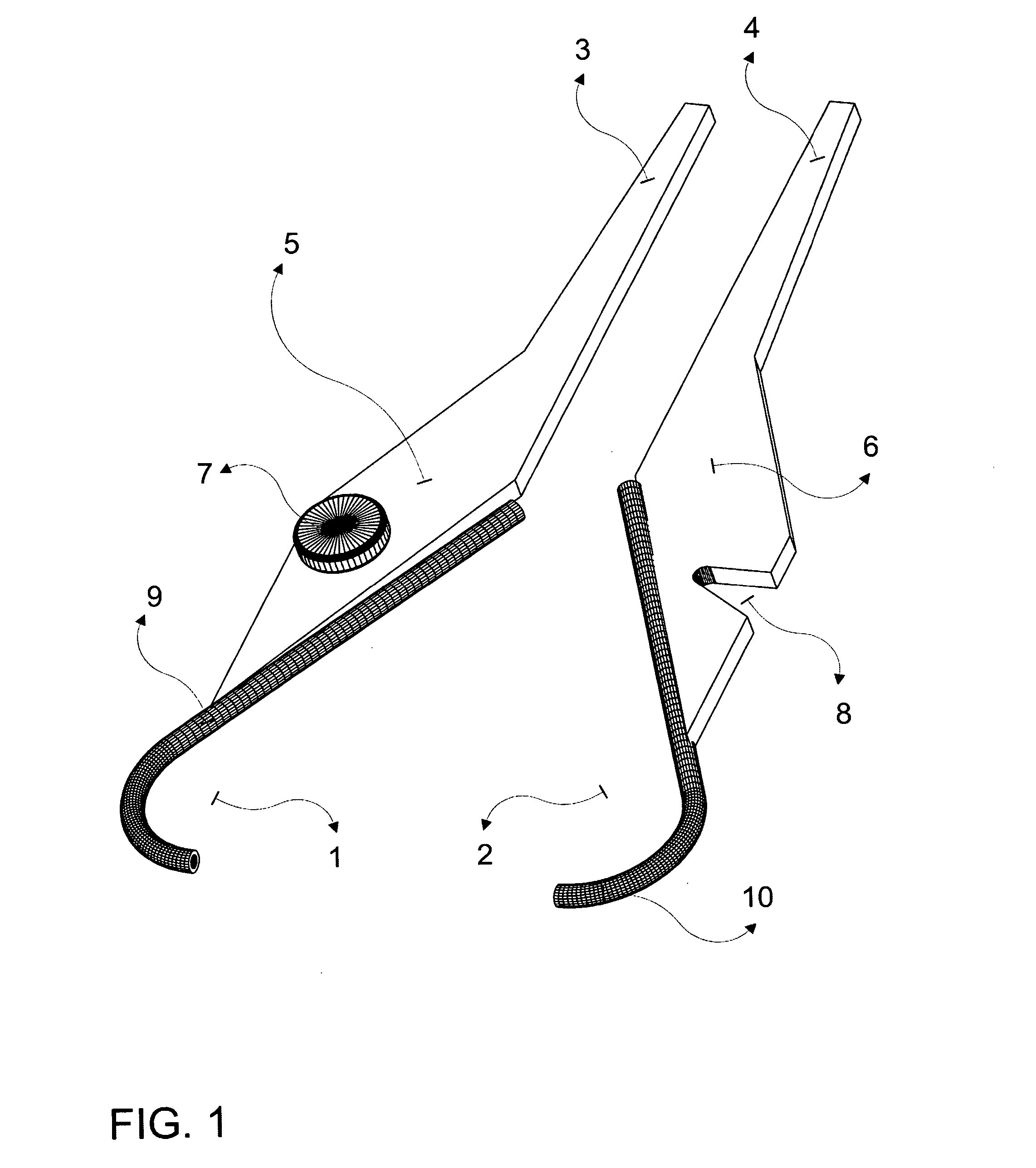
[0031]FIG. 1 shows the preferred embodiment of the bone cerclage tool of the present invention, designated generally by the reference number 16. The wire / cable passer 16 has two members 1,2. Each member includes: a handle 3,4 to grip the tool and to firmly couple both members when both handles 3,4 are pulled close; a central part 5,6; and a J shaped tube 9,10. One of the members 1 of the bone cerclage tool 16, includes a button 7 on its central part 5, while the other member 2 includes a notch 8 in its central part 6.

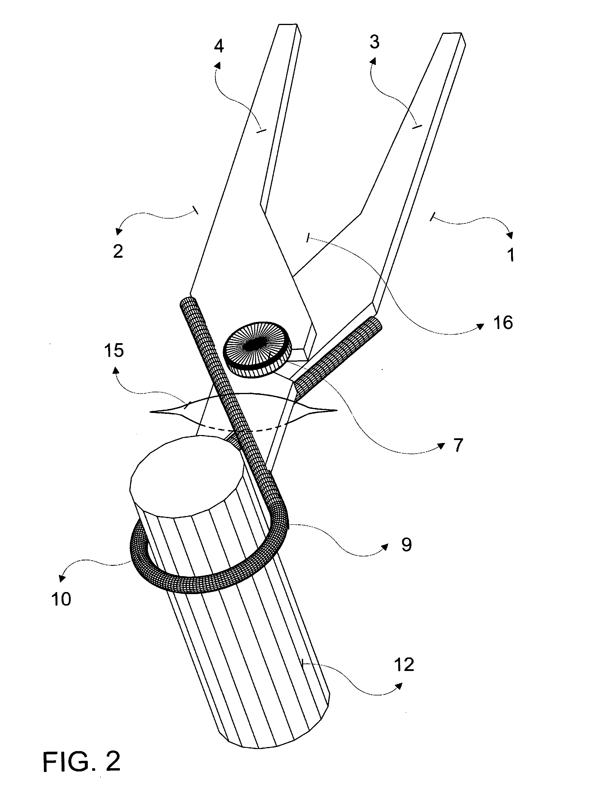
[0032] As it is clearly seen in FIG. 2, after both members 1,2 are coupled together, J shaped tubes 9,10 conform a continuous tube through which a wire 11 cable, band or suture can be fed.

[0033] The surgical procedure is described hereinto with reference to FIGS. 3-6.

[0034] During surgical procedures each member...


PUM

PropertyMeasurementUnit
Fractionaaaaaaaaaa
Lengthaaaaaaaaaa

Abstract

A bone cerclage tool for conformally slidably abut a device circumferentially against a bone, such that unnecessary exposure or stripping of soft tissue away from the bone and/or significant spreading of the incision is minimized. This bone cerclage tool makes very simple to encircle a bone with a suture, wire, cable, band, or device, to secure the bone in place, or perform operations on the bone and/or in the vicinity of the bone. The bone cerclage tool includes two parts, wherein each part comprises a bent tube with a length not sufficient to completely surround the bone. When both parts are coupled together, the cerclage instrument becomes a single tube, allowing the wire to be slid around the bone in a very simple way. After the wire/cable is slid through the tube, the instrument can be disassembled, leaving the wire around the bone ready to be tightened.

Description

CROSS-REFERNCE TO RELATED APPLICATIONS [0001] Not applicable. STATEMENT REGARDING FEDERALLY SPONSORED RESEARCH OR DEVELOPMENT [0002] Not applicable. REFERENCE TO SEQUENCE LISTING, A TABLE, OR A COMPUTER PROGRAM LISTING COMPACT DISC APPENDIX [0003] Not applicable. BACKGROUND OF THE INVENTION [0004] The present invention is directed to a cerclage tool, and in particular to an instrument used to position a cerclage wire around a bone for fixation of a fracture such that when the instrument is inserted into the patient, the disruption of surrounding muscle tissue is minimal. [0005] The use of cerclage wires for internal fixation of bone fractures is a well-known technique. Cerclage wiring techniques are frequently used following reduction for provisional fixation of long bone fractures to stabilize the bone for placement of screws, nails or rods, after which the wires are removed. They may also be used for definitive bone fixation, either alone or in combination with other fixation devi...

Claims


Application Information

Patent Timeline
IPC IPC(8): A61B17/58
CPCA61B17/82A61B17/842A61B17/8861Y10T29/539
Inventor FERNANDEZ, ALBERTO ANGEL
Owner SYNTHES GMBH
Why Eureka
Try Eureka