
Speed measurement system for speed control of high-speed motors

a technology of high-speed motors and measurement systems, which is applied in fluid speed measurement, digital computer details, instruments, etc., can solve problems such as system instability, motor heating, and speed fluctuations

Inactive Publication Date: 2007-02-22
GM GLOBAL TECH OPERATIONS LLC
View PDF4 Cites 32 Cited by
  • Summary
  • Abstract
  • Description
  • Claims
  • Application Information

AI Technical Summary

Benefits of technology

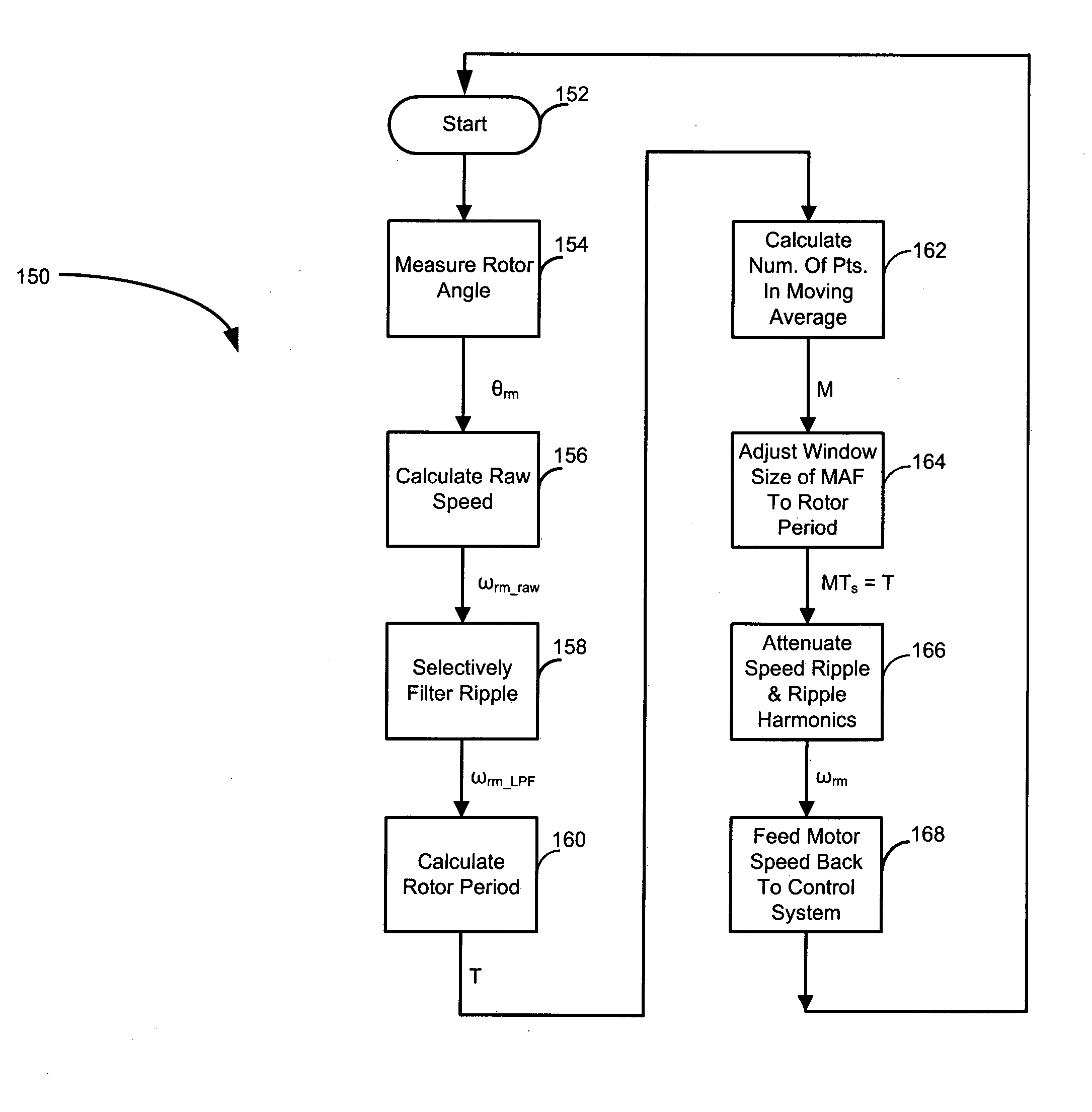
[0016] In another feature, a moving average filter removes ripple and harmonics of the ripple from the raw speed of the motor.

Problems solved by technology

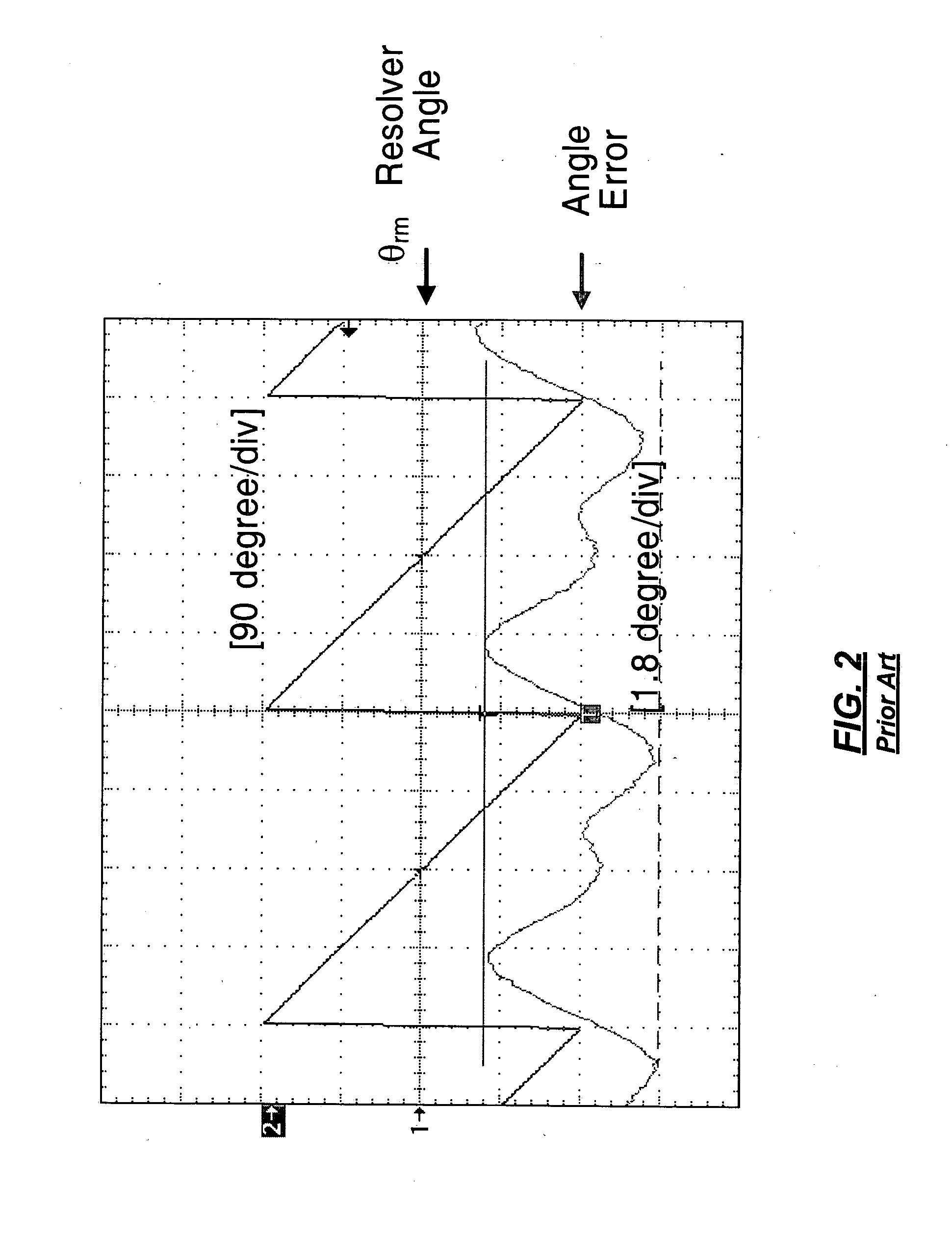
The motor speed should be accurately measured because errors in measured speed are fed back to the control system and can cause speed fluctuations, system instability, and motor heating.
This renders the control system unstable.
The ripple in motor speed also causes heating and loss due to harmonics.
Therefore, motor speed fluctuation, control system instability, and motor heating are high at high motor speeds.
The cut-off frequency of the filter, however, cannot be set so low as to completely eliminate the ripple because the low cut-off frequency causes delay in the feedback loop.
This method, however, sacrifices control dynamics and is therefore inadequate for speed control of high-speed motors.

Method used


Image

  • Speed measurement system for speed control of high-speed motors
  • Speed measurement system for speed control of high-speed motors
  • Speed measurement system for speed control of high-speed motors

Examples


Embodiment Construction

[0034] The following description of the preferred embodiment(s) is merely exemplary in nature and is in no way intended to limit the invention, its application, or uses. For purposes of clarity, the same reference numbers will be used in the drawings to identify similar elements. As used herein, the term module, controller and / or device refers to an application specific integrated module (ASIC), an electronic module, a processor (shared, dedicated, or group) and memory that execute one or more software or firmware programs, a combinational logic module, and / or other suitable components that provide the described functionality.

[0035] Referring now to FIG. 6, a motor speed control system 100 includes a motor 22. A position sensor, such as a resolver 24 or an encoder (not shown), and a signal processing module 26 measure rotor angle θrm. A speed measurement module 110 determines motor speed ωrm from the rotor angle. A comparator module 30 determines the difference between the measured...


PUM


Abstract

A system for measuring speed of a high-speed motor using a moving average filter. A position sensor generates a rotor position signal. A signal processing module determines a rotor angle from the rotor position signal. A speed observer module calculates a raw speed of the motor from the rotor angle. A filter module selectively generates a filtered speed of the motor from the raw speed of the motor. A frequency-to-period converter module calculates a rotor period from one of the raw speed of the motor and the filtered speed of the motor. A divider module calculates number of points in a moving average from the rotor period. A moving average filter module adjusts a window size of the moving average to the rotor period. A moving average filter removes ripple and harmonics of the ripple from the raw speed of the motor.

Description

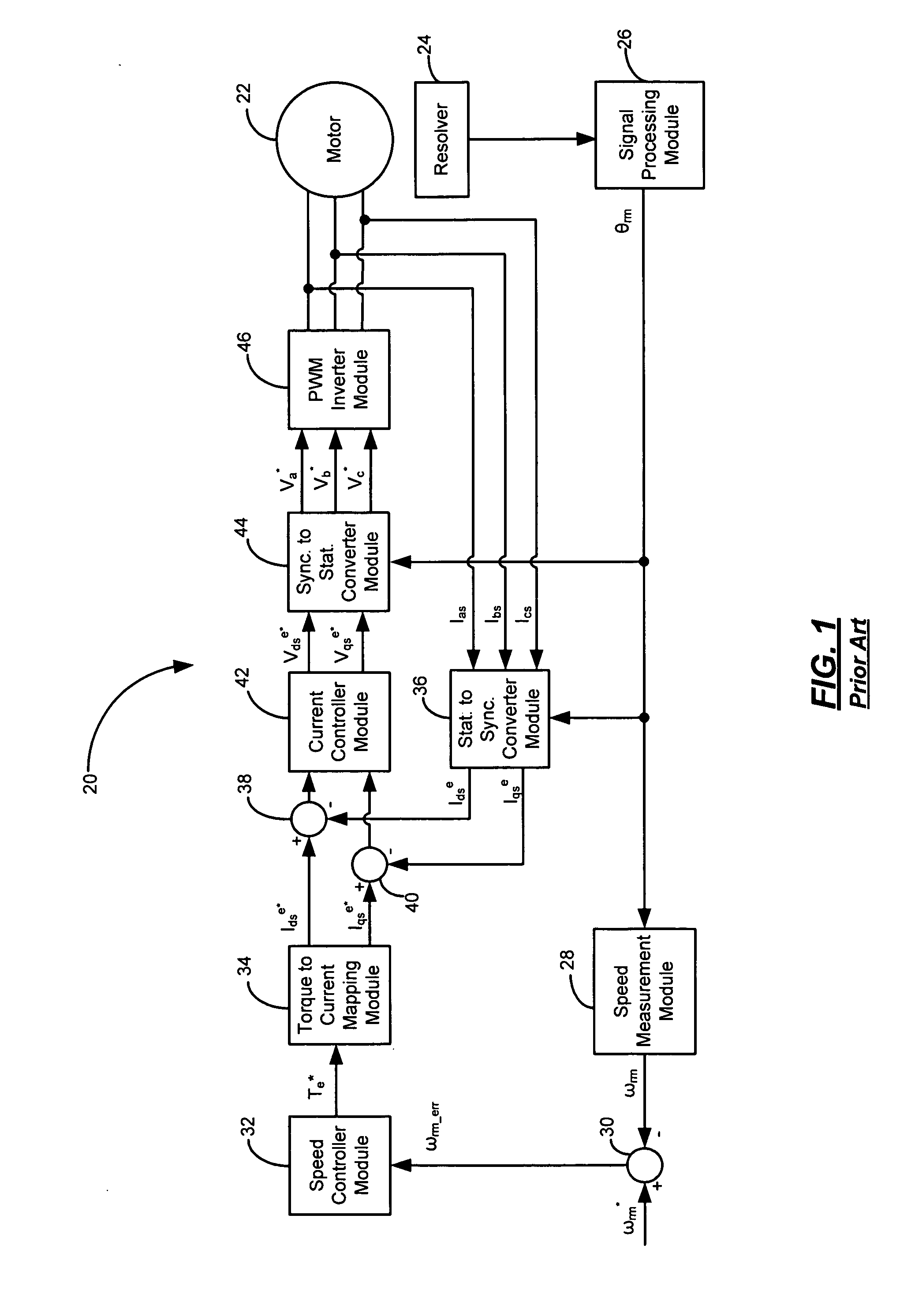
FIELD OF THE INVENTION [0001] The present invention relates to speed control of high-speed motors, and more particularly to systems and methods for measuring speed of high-speed AC motors. BACKGROUND OF THE INVENTION [0002] In a feedback control system used to control speed of a motor, the speed of the motor is measured and fed back to the control system. FIG. 1 shows a typical system 20 that controls speed of an AC motor 22. A rotor position sensor, such as a resolver 24 or an encoder (not shown), and a signal processing module 26 measure rotor angle θrm. A speed measurement module 28 determines motor speed ωrm from the rotor angle. A comparator module 30 determines the difference ωrm<sub2>—< / sub2>err between the measured speed ωrm and a command speed ωrm*. The difference is fed to a speed controller module 32 that generates a torque command Te* to minimize the difference. Based on the torque command, a torque-to-current mapping module 34 generates command currents Idse...

Claims


Application Information

Patent Timeline
IPC IPC(8): G01P3/00
CPCG01P3/48G01P3/488H02P21/00H02P21/18
Inventor BAE, BON-HO
Owner GM GLOBAL TECH OPERATIONS LLC
Learn More