

Skid resistant surfaces
a technology of skid resistance and surface, applied in the direction of floor coverings, treads, roof coverings using flexible materials, etc., can solve the problems of difficult or impossible to unroll the underlayment, difficulty in maintaining unrollability, etc., and achieve excellent skid or slip resistance, easy installation, and easy rolling
- Summary
- Abstract
- Description
- Claims
- Application Information
AI Technical Summary
Benefits of technology
Problems solved by technology
Method used
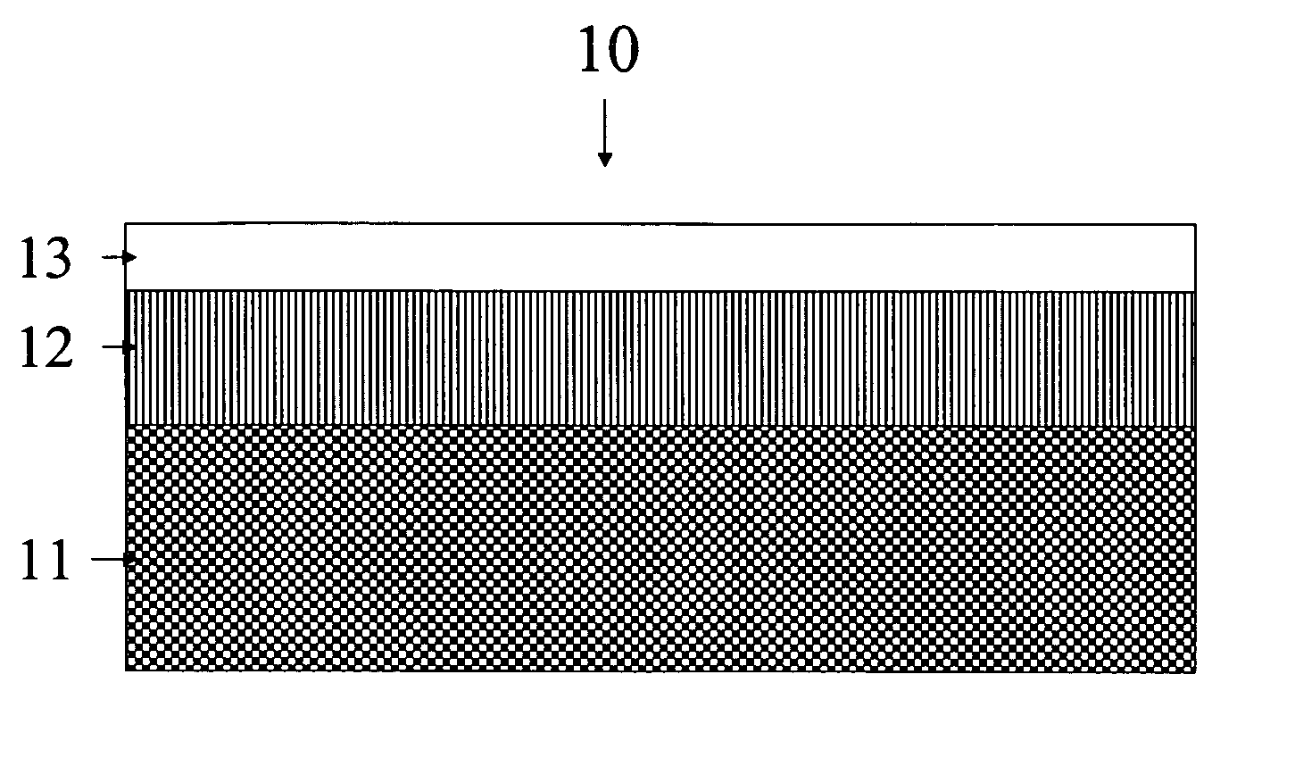
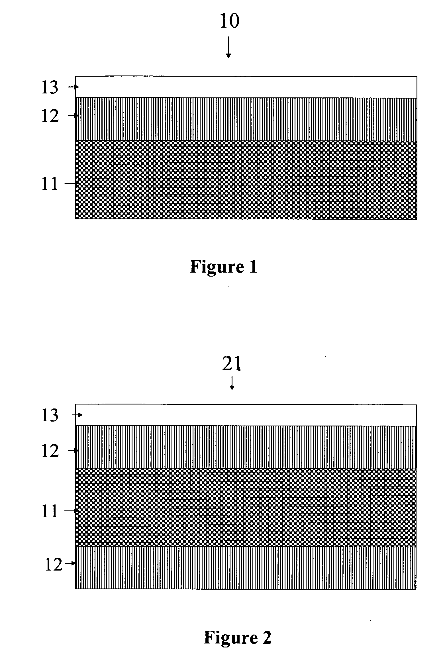
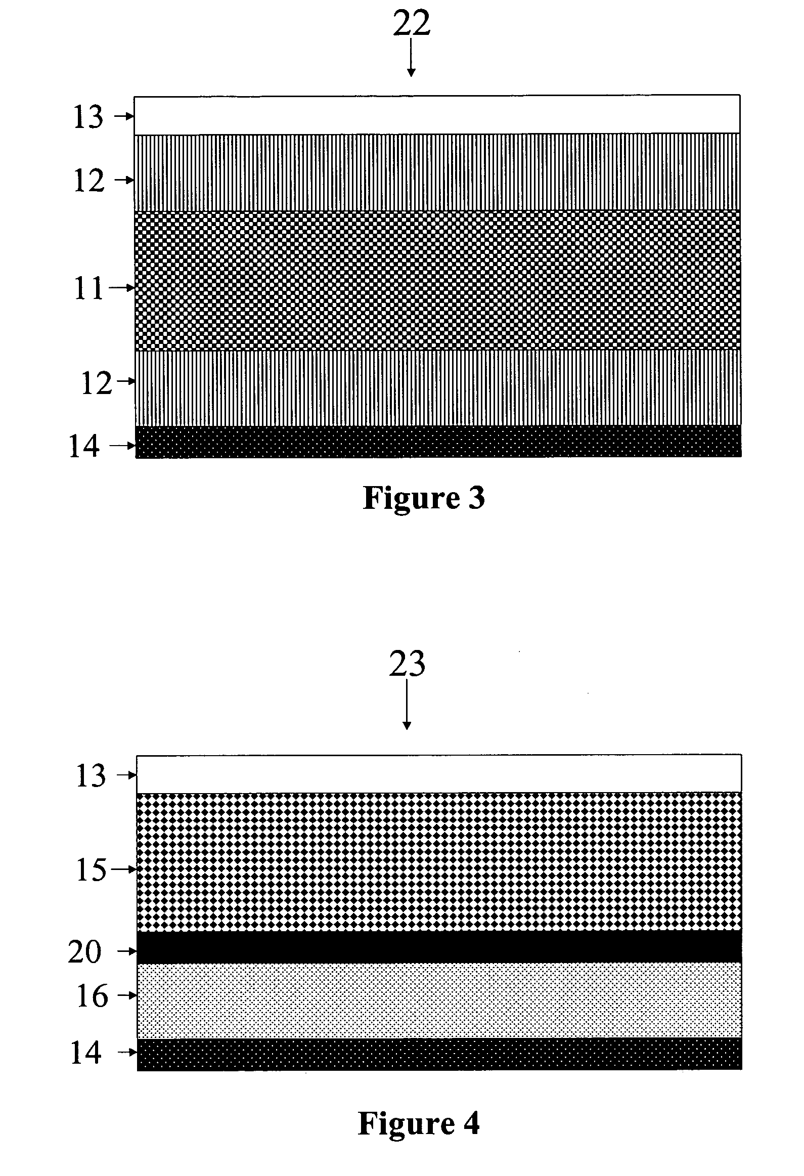
Image

Examples
example 1
[0090] A blocking test was conducted, which is a severe test designed to develop an understanding of blocking on a relative basis. A control membrane, a polyolefin (PO) coated non-woven is easily unrolled. The polyolefin coated control membrane comprises a 2 oz / yd non-woven polypropylene fabric coated on each side with 1.25 mils coex layer. On the side in contact with the skid-resistant layer the coex layer comprise 1.0 mil layer PP / LDPE blend and a 0.25 mils layer comprising a copolymer of ethylene and methyl acrylate. The thin layer faces outward. The coex layer on the other side of the non-woven comprises a 1 mil layer of a PP / LDPE blend and a 0.25 mil layer comprising an ethylene / propylene copolymer. The thin layer faces outward. If an experimental membrane exhibits an ability to unroll as easily or more easily versus the control in the accelerated test, than it is assumed that the experimental membrane will unroll easier than the control under normal circumstances.
[0091] The a...
example 2
[0097] Skid resistance was measured in a “walk on” test as follows. Underlayment specimens to be tested were mechanically attached to a sheet of plywood and positioned at a test angle of 40°. The samples were sprayed with water prior to testing. A tester (“walker”) walks over the sample and compares the wet skid resistance of the sample to a “control”, which was a membrane comprising a 2 side polyolefin-coated polypropylene non-woven described above. The “walker” judges the sample membrane to exhibit better, similar or worse skid resistance versus the control membrane. The results for various underlayments tested are shown in Table 1. Samples 1-13 are embodiments of the present invention and all exhibit superior wet skid resistance in comparison to the control membrane. It's also important to note that water-based binders comprising a surfactant impart poor wet skid resistance. See test results for specimens 25 to 27 in Table 1 where all of the non-skid layers are acrylic emulsions ...
example 3
[0098] Adhesion of the non-skid coating to the support sheet is measured in a peel adhesion test using a pre-formed pressure sensitive tape. A 2″ wide preformed tape, “Preprufe® Tape”, is applied to the non-skid coated face of the underlayment. The sample is rolled 4 times, at 1 second per pass, with a 30 lb roller. Adhesion is measured in a T-peel adhesion test 15 min after rolling at a cross head speed of 2″ per minute with an Instron mechanical tester. Results for various underlayments comprising a woven polypropylene mesh coated with a filled textured binder are shown in Table 2. Note that all underlayments, except for that comprising gilsonite, passes the minimum adhesion requirement for an underlayment comprising a filled textured binder. Also note that the 3 underlayments comprising the acrylic emulsion binders in the non-skid layer also pass the minimum adhesion requirement. However, these underlayments exhibit poor wet skid resistance as noted in example 2 because these bin...
PUM
| Property | Measurement | Unit |
|---|---|---|
| thick | aaaaa | aaaaa |
| thick | aaaaa | aaaaa |
| width | aaaaa | aaaaa |
Abstract
Description
Claims
Application Information