Fuel nozzle for gas turbine engines

a technology of gas turbine engines and fuel nozzles, which is applied in the ignition of turbine/propulsion engines, engine starters, lighting and heating apparatus, etc., can solve the problems of insufficient purge air supply of compressors, relatively small purge flow, and insufficient protection

Active Publication Date: 2007-03-01
GENERAL ELECTRIC CO
View PDF6 Cites 31 Cited by
  • Summary
  • Abstract
  • Description
  • Claims
  • Application Information

AI Technical Summary

Problems solved by technology

However, when the steam injection system is not in use, i.e. during dry operation, at least one known gas turbine engine utilizes at least one of an air or fuel purge to reduce the potential for cross-talk between adjacent fuel nozzles and / or to reduce backflow into the fuel nozzle caused by off-board steam system leakage.
More specifically, at least one known gas turbine engine includes a relatively large steam circuit flow area, such that compressor discharge bleed air supply is insufficient to purge the fuel nozzles.
Similarly, utilizing gas to purge the fuel nozzle results in a relatively small purge flow, which is insufficient to provide protection against the aforementioned situations.

Method used


Image

  • Fuel nozzle for gas turbine engines
  • Fuel nozzle for gas turbine engines
  • Fuel nozzle for gas turbine engines

Examples


Embodiment Construction

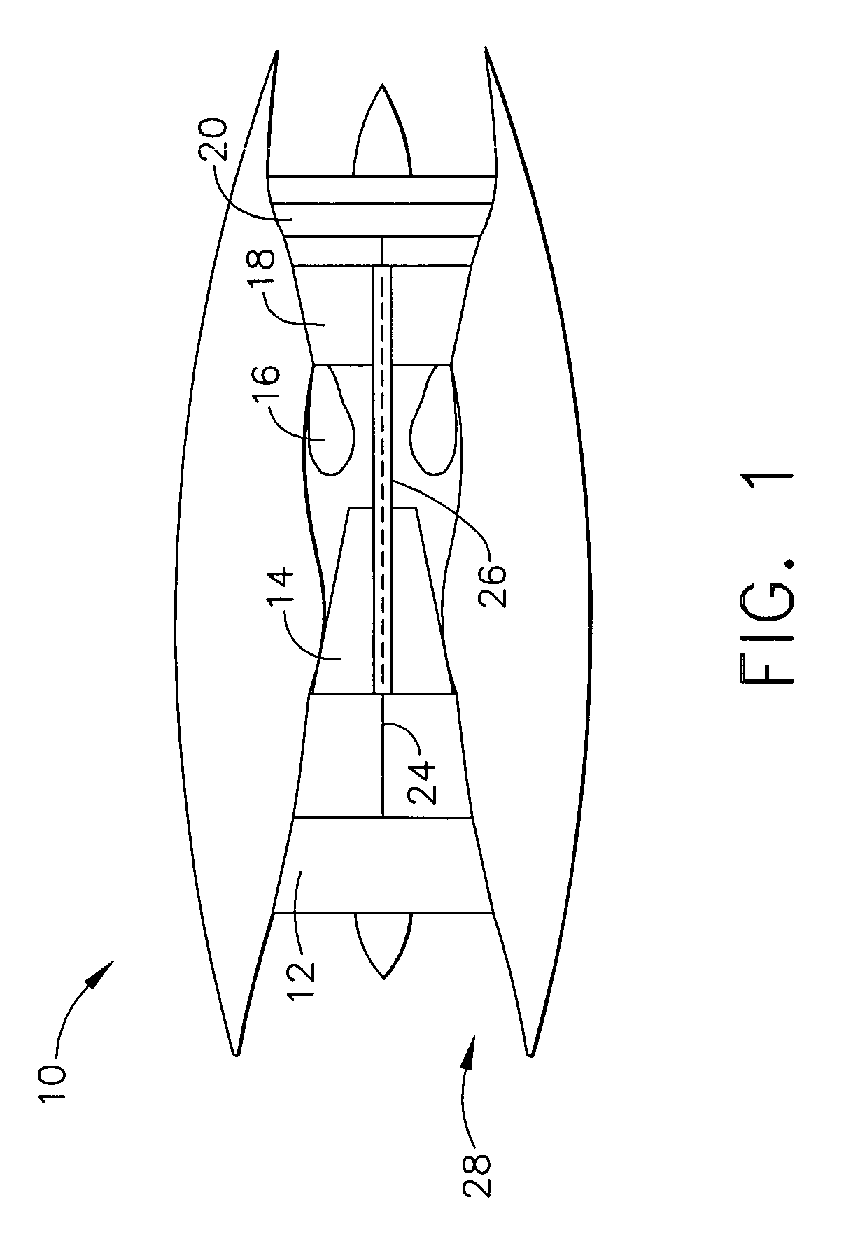
[0014]FIG. 1 is a schematic illustration of an exemplary gas turbine engine 10 including a low pressure compressor 12, a high pressure compressor 14, and a combustor 16. Engine 10 also includes a high pressure turbine 18, and a low pressure turbine 20 arranged in a serial, axial flow relationship. Compressor 12 and turbine 20 are coupled by a first shaft 24, and compressor 14 and turbine 18 are coupled by a second shaft 26. In one embodiment, gas turbine engine 10 is an LMS100 engine commercially available from General Electric Company, Cincinnati, Ohio.

[0015] In operation, air flows through low pressure compressor 12 from an upstream side 28 of engine 10. Compressed air is supplied from low pressure compressor 12 to high pressure compressor 14. Highly compressed air is then delivered to combustor assembly 16 where it is mixed with fuel and ignited. Combustion gases are channeled from combustor assembly 16 to drive turbines 18 and 20.

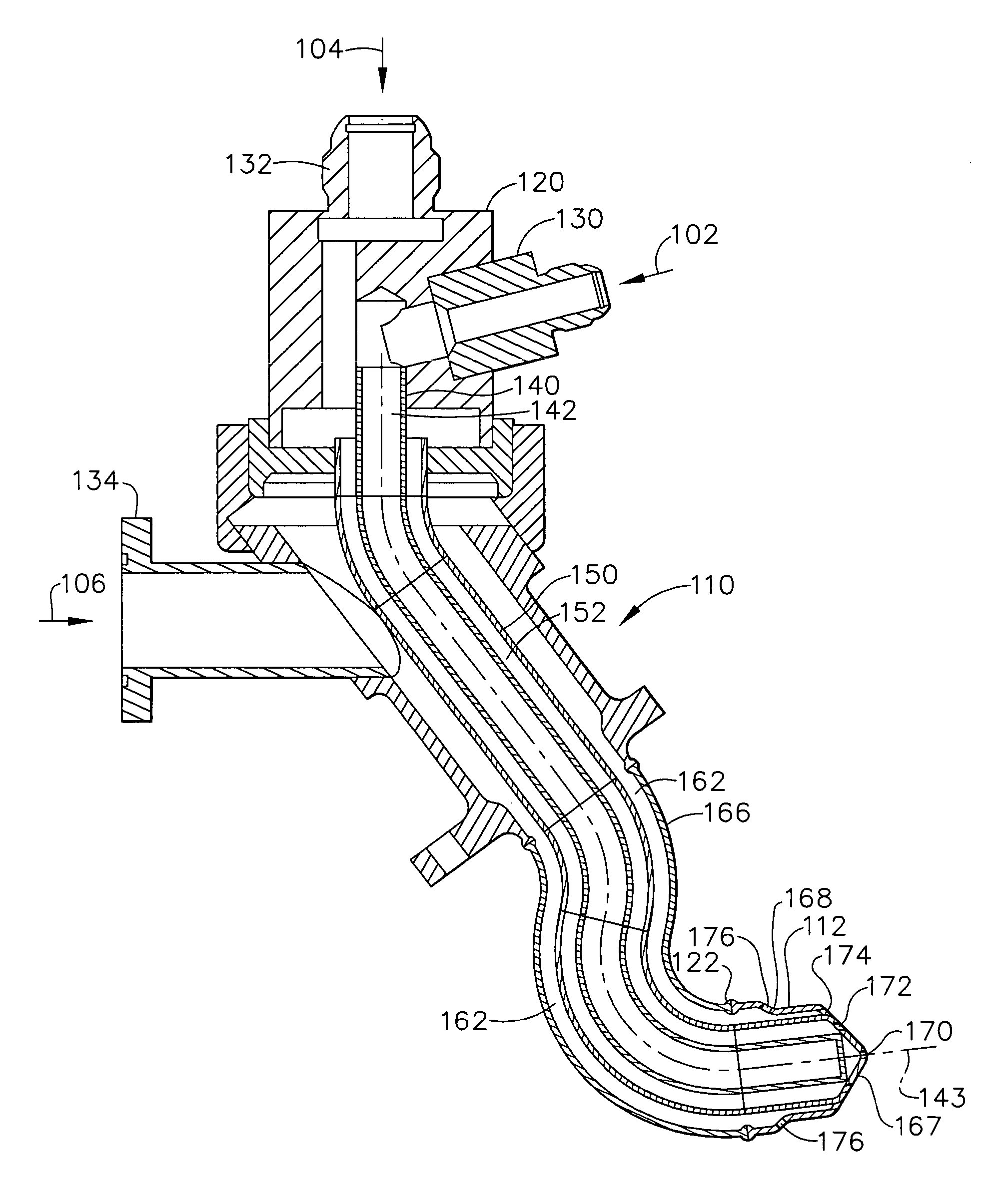
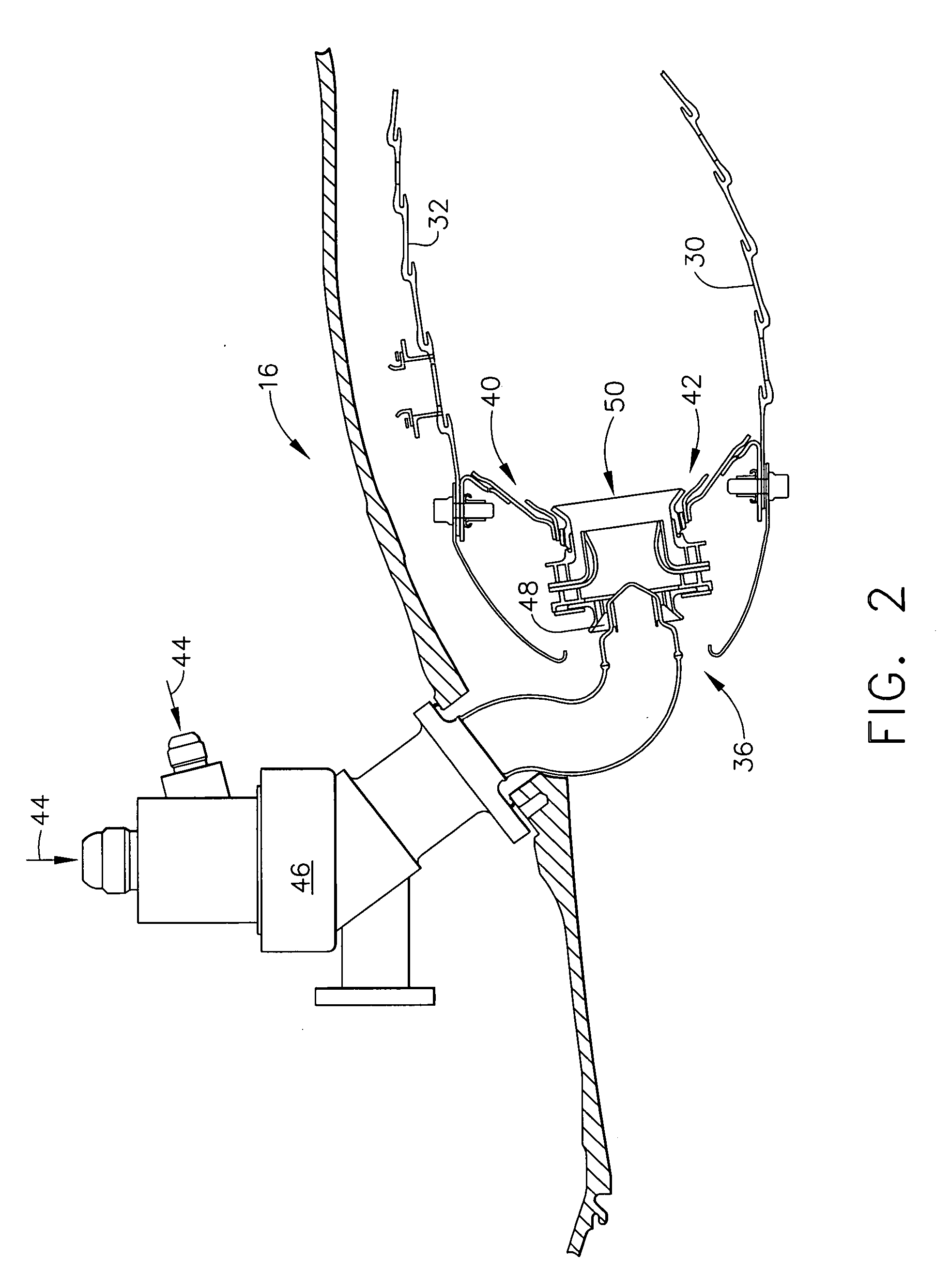
[0016]FIG. 2 is a cross-sectional view of a com...


PUM


Abstract

A gas turbine engine fuel nozzle includes an axis of symmetry extending therethrough, the nozzle body including a first passage extending coaxially therethrough, a second passage, and a third passage, the second passage circumscribing the first passage, the third passage formed radially outward of the second passage, and a nozzle tip coupled to the nozzle body, the nozzle tip including at least one primary discharge opening in flow communication with the first passage, at least one secondary discharge opening in flow communication with the second passage, and at least one tertiary discharge opening in flow communication with the third passage.

Description

BACKGROUND OF THE INVENTION [0001] This invention relates generally to gas turbine engines and, more particularly, to a fuel nozzle for a gas turbine engine. [0002] Air pollution concerns worldwide have led to stricter emissions standards both domestically and internationally. Pollutant emissions from industrial gas turbines are subject to Environmental Protection Agency (EPA) standards that regulate the emission of oxides of nitrogen (NOx), unburned hydrocarbons (HC), and carbon monoxide (CO). In general, engine emissions fall into two classes: those formed because of high flame temperatures (NOx), and those formed because of low flame temperatures that do not allow the fuel-air reaction to proceed to completion (HC & CO). [0003] Accordingly, at least one known industrial gas turbine application includes a steam injection system that is configured to inject steam into the combustor to facilitate reducing nitrous oxide emissions from the gas turbine engine. However, when the steam i...

Claims


Application Information

Patent Timeline
Patent Type & Authority Applications(United States)
IPC IPC(8): F02C7/22
CPCF23D11/24F23D11/386F23D2209/30F23D2214/00F23L7/005F23L7/007F23R3/14F23R3/286F23R3/36Y02E20/344Y02E20/34
Inventor HELD, TIMOTHYCOOPER, JAMES
Owner GENERAL ELECTRIC CO
Why Eureka
Try Eureka