Layout structure of hydraulic control valve for valve train in internal combustion engine

a technology of hydraulic control valve and internal combustion engine, which is applied in the direction of non-mechanical valves, machines/engines, mechanical apparatus, etc., can solve the problems of large influence of heat from the cylinders on the hydraulic control valve, impaired external appearance of the internal combustion engine, and prone to stay in this space of the cylinders, so as to reduce the accuracy of valve timing

Inactive Publication Date: 2007-03-01
HONDA MOTOR CO LTD
View PDF3 Cites 14 Cited by
  • Summary
  • Abstract
  • Description
  • Claims
  • Application Information

AI Technical Summary

Benefits of technology

[0007] However, the space below the induction system of the V-type internal combustion engine is a space defined between V-banked cylinders. The heat from the cylinders directly influences this space. Furthermore, this space is confined both in the vertical direction and in the longitudinal direction (or the lateral direction) of a vehicle that includes the en...

Problems solved by technology

Therefore, the heat from the cylinders is prone to stay in this space.
Accordingly, when the hydraulic control valve is located in this space, the influence of heat from the cylinders upon the hydrau...

Method used


Image

  • Layout structure of hydraulic control valve for valve train in internal combustion engine
  • Layout structure of hydraulic control valve for valve train in internal combustion engine
  • Layout structure of hydraulic control valve for valve train in internal combustion engine

Examples


Embodiment Construction

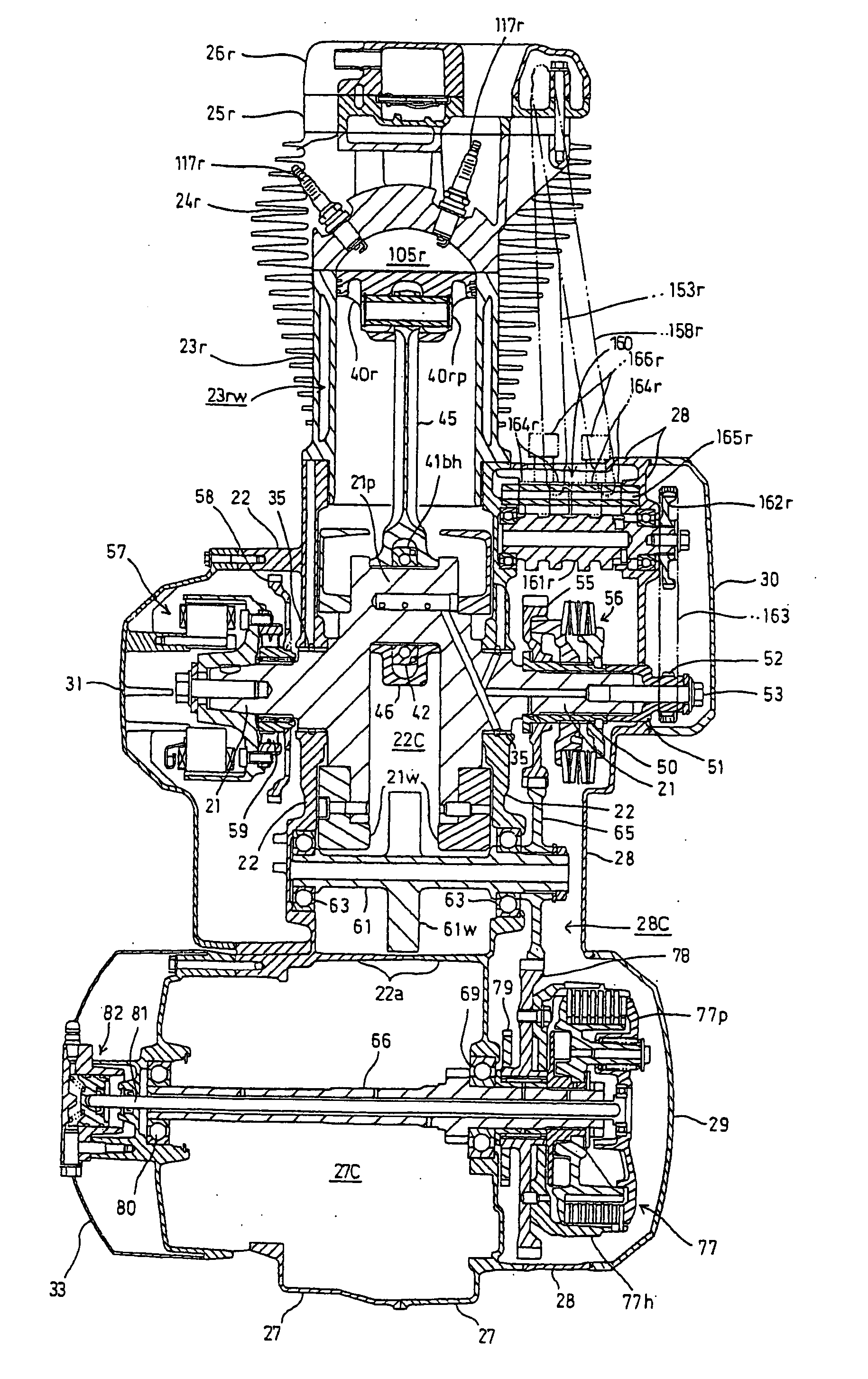
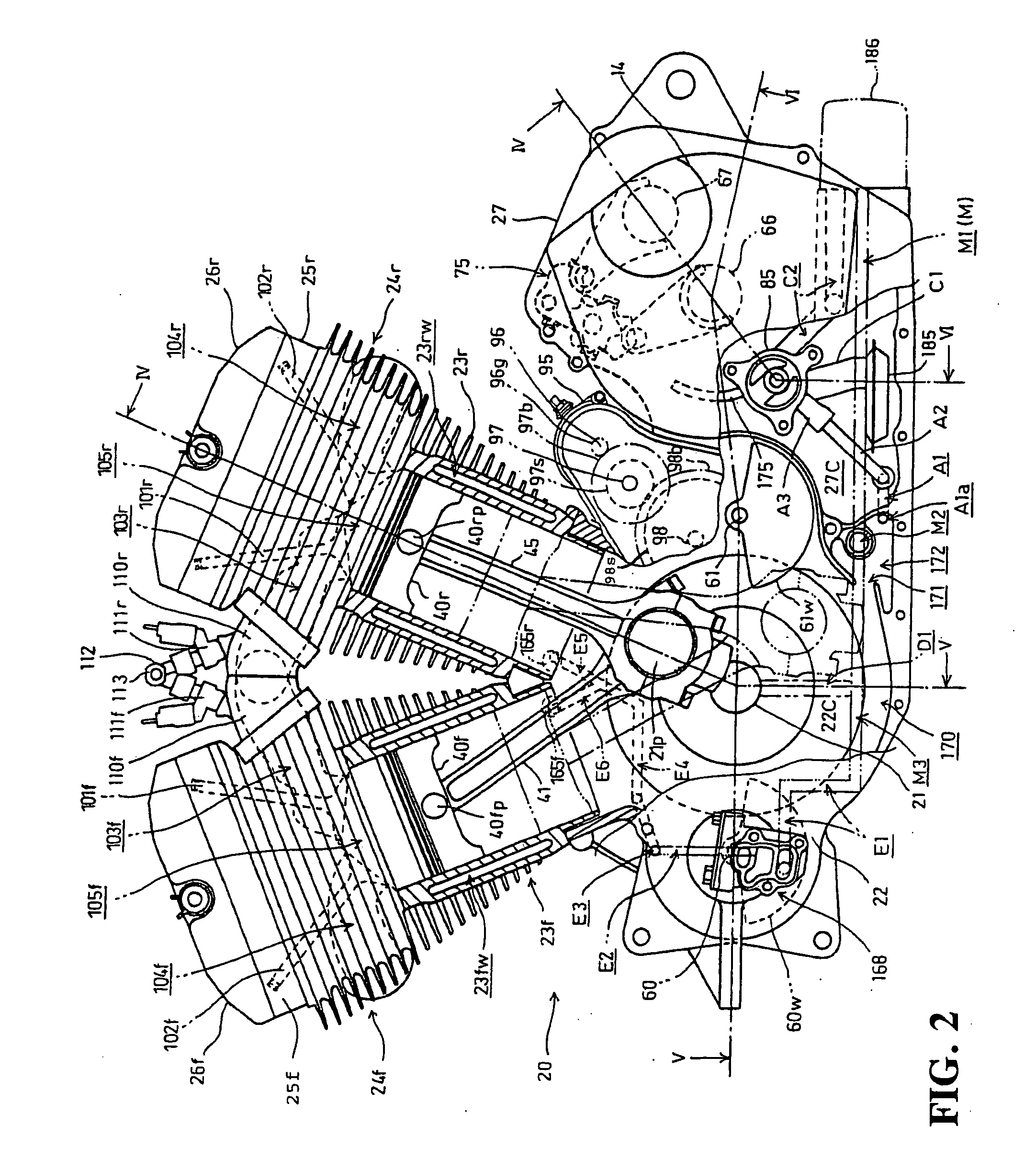
[0035] An embodiment of the present invention will now be described with reference to the accompanying drawings. The same reference numerals will be used to identify the same or similar elements throughout the several views. It should be noted that each of the drawings should be viewed in the direction of orientation of the reference numerals.

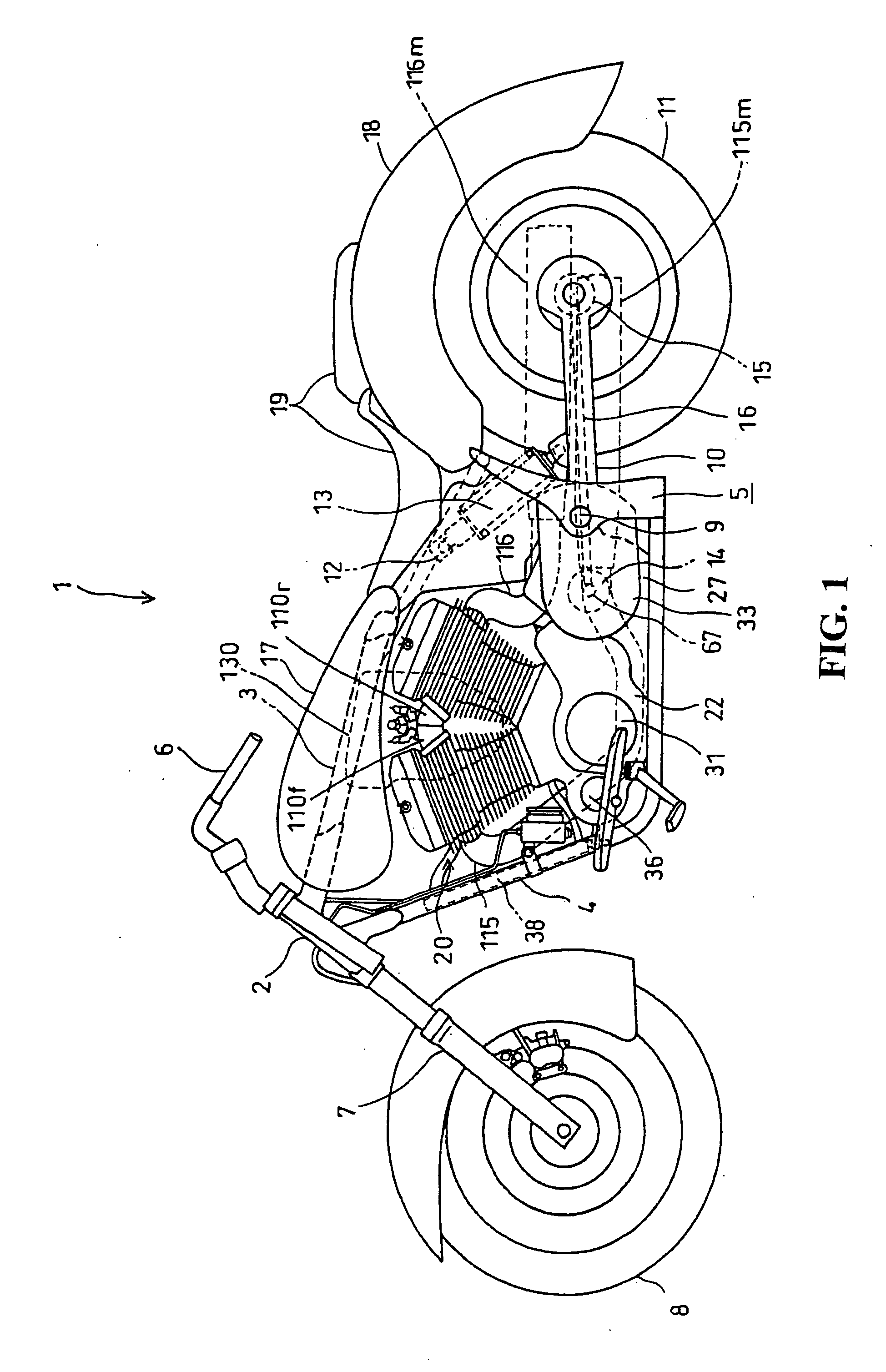
[0036] A preferred embodiment of the present invention will now be described with reference to FIGS. 1 to 12. FIG. 1 is a general side view of a motorcycle 1 including an internal combustion engine 20 according to a preferred embodiment of the present invention. The motorcycle 1 has a head pipe 2 and a main frame 3 extending rearward from the head pipe 2. A pair of right and left down tubes 4 extend downward from the head pipe 2 below the main frame 3 and further extend rearward from a lower bent portion of the down tubes 4. A radiator 38 is supported between the right and left down tubes 4.

[0037] The main frame 3 is bifurcated at an intermed...


PUM


Abstract

To provide a layout structure of a hydraulic control valve for a valve train in an internal combustion engine which can reduce the influence of heat from the cylinders and can avoid the impairment of the external appearance of the internal combustion engine. An internal combustion engine has a valve operation characteristics changing mechanism that changes the operation characteristics of at least one of an intake valve and an exhaust valve. A hydraulic control valve for a valve train controls the pressure of a hydraulic fluid supplied to the valve operation characteristics changing mechanism. The hydraulic control valve is located on the left side surface of right and left crankcases that support and cover a crankshaft at a position below cylinders.

Description

CROSS-REFERENCE TO RELATED APPLICATIONS [0001] This nonprovisional application claims priority under 35 U.S.C. §119(a) on Patent Application Nos. 2005-251805 and 2006-120503, filed in Japan on Aug. 31, 2005 and Apr. 25, 2006, respectively. The entirety of each of the above-identified applications is incorporated herein by reference. BACKGROUND OF THE INVENTION [0002] 1. Field of the Invention [0003] The present invention relates to a layout structure of a hydraulic control valve for a valve train in an internal combustion engine. [0004] 2. Description of Background Art [0005] An internal combustion engine has a valve train that has operation characteristics that can be changed by a hydraulic control valve. A layout structure of the hydraulic control valve is disclosed in Japanese Patent Laid-Open No. 2002-180812, for example. [0006] In Japanese Patent Laid-Open No. 2002-180812, the hydraulic control valve is located in a space below an induction system extending from V-banked cylind...

Claims


Application Information

Patent Timeline
IPC IPC(8): F01L1/34F01L1/14
CPCF01L1/146F01L1/34F02B61/02F02F7/0012F16C7/023
Inventor KONO, NAOKITAKAHASHI, ISAMU
Owner HONDA MOTOR CO LTD
Why Eureka
Try Eureka