Multichannel, surface parallel, zonal transducer system

Active Publication Date: 2007-03-01
NORTHROP GRUMMAN SYST CORP
View PDF5 Cites 21 Cited by
  • Summary
  • Abstract
  • Description
  • Claims
  • Application Information

AI Technical Summary

Benefits of technology

[0007] It is a further object of this invention to provide such an improved multichannel, surface parallel, zonal, transducer system which when applied to drive an adaptive optic component has more stroke, even with thick coatings, higher correction frequency, a wider range of spatial frequency response, with more stiffness and stability and requiring lower

Problems solved by technology

And the coatings can cause further stress and deformation.
The amount of motion is limited, usually no more than 1½-2 um, and often is not sufficient to compensate for even these inherent deformations let alone other environmentally caused deformation

Method used


Image

  • Multichannel, surface parallel, zonal transducer system
  • Multichannel, surface parallel, zonal transducer system
  • Multichannel, surface parallel, zonal transducer system

Examples


Example

[0026] Aside from the preferred embodiment or embodiments disclosed below, this invention is capable of other embodiments and of being practiced or being carried out in various ways. Thus, it is to be understood that the invention is not limited in its application to the details of construction and the arrangements of components set forth in the following description or illustrated in the drawings. If only one embodiment is described herein, the claims hereof are not to be limited to that embodiment. Moreover, the claims hereof are not to be read restrictively unless there is clear and convincing evidence manifesting a certain exclusion, restriction, or disclaimer.

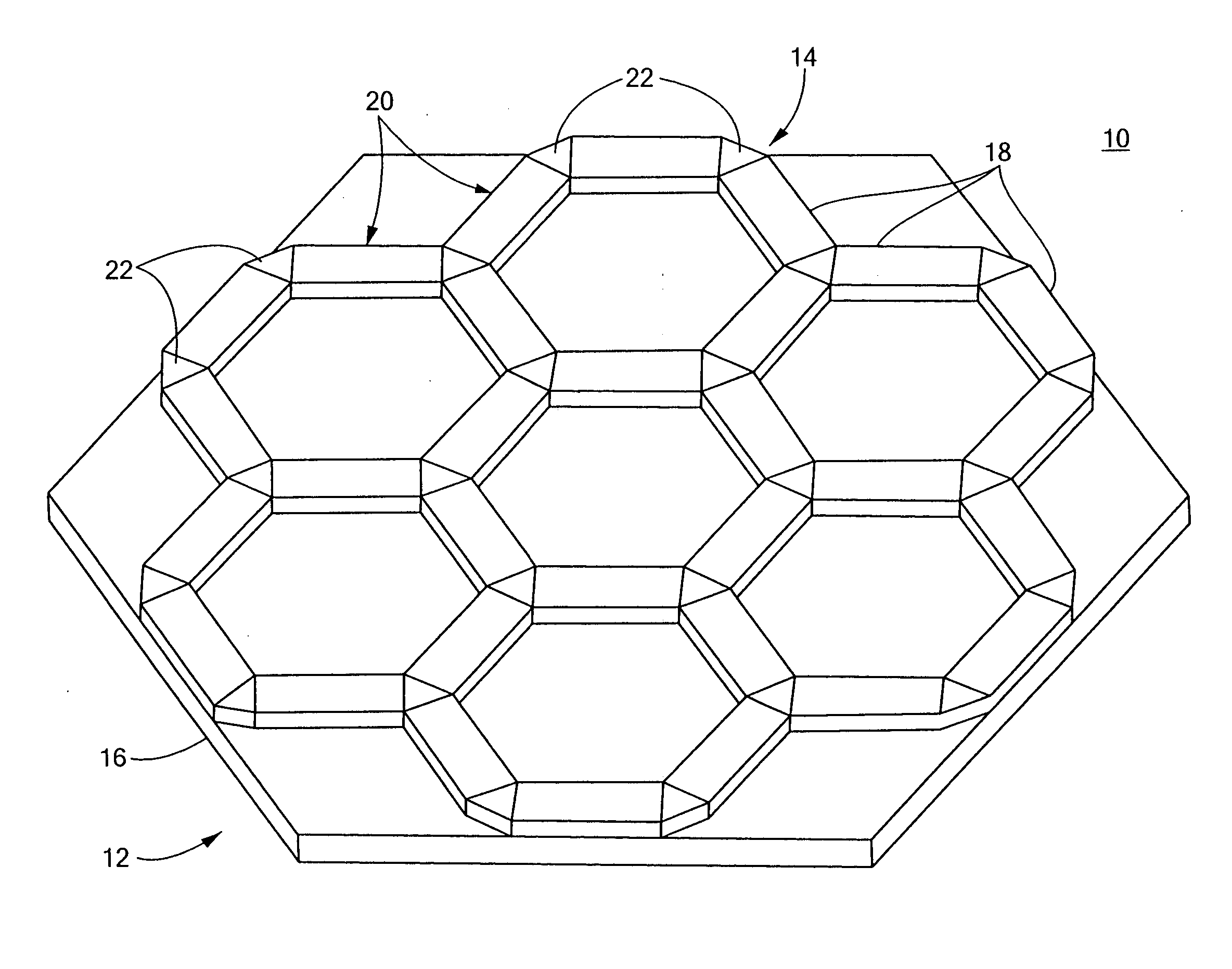
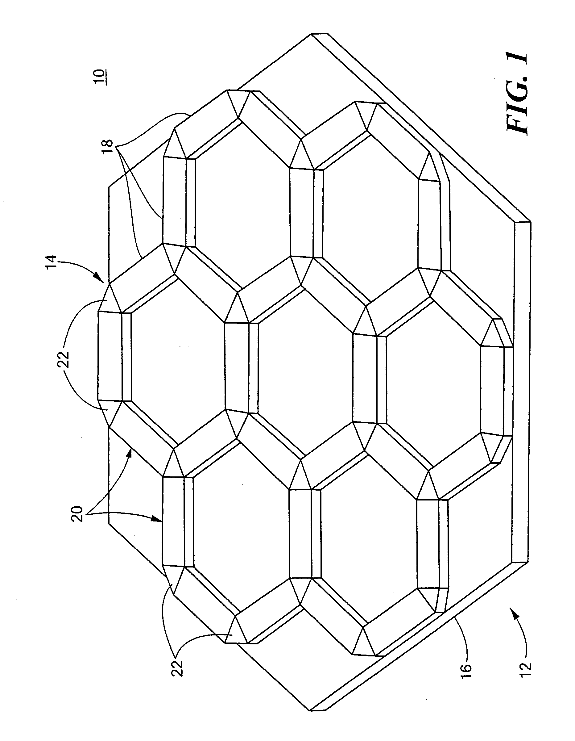
[0027] There is shown in FIG. 1 a multichannel, surface parallel, zonal transducer system 10 according to this invention including a membrane 12 and a compound transducer 14 mounted on the membrane. The transducer may be an actuator or a sensor and can have any number of applications. For example, as an acoustic or audio ...


PUM


Abstract

A multichannel, surface parallel, zonal transducer system includes a membrane and a compound transducer mounted on the membrane, the compound transducer including a plurality of transducer elements extending generally parallel to the membrane, interconnected in a closed network and individually addressable.

Description

FIELD OF THE INVENTION [0001] This invention relates to a multichannel, surface parallel, zonal transducer system, and more particularly to such a transducer system useful in adaptive optic systems. BACKGROUND OF THE INVENTION [0002] Multichannel, surface parallel, zonal transducer systems are often used for controlling light weight adaptive optics. In one approach a MEMS device consisting of individual actuators of piezoelectric, ferroelectric or capacitive material are mounted on one side of an optical membrane. Optical coatings are often applied to the optical surface on the other side of the membrane. This approach suffers from a number of shortcomings. The mass of the actuators themselves suspended from the membrane distort the membrane. And the coatings can cause further stress and deformation. The amount of motion is limited, usually no more than 1½-2 um, and often is not sufficient to compensate for even these inherent deformations let alone other environmentally caused defo...

Claims


Application Information

Patent Timeline
IPC IPC(8): G02B26/08H02N2/00G01D5/12
CPCG02B26/06H01L41/083H01L27/20H10N39/00H10N30/50
Inventor PEARSON, DAVID D.CAVACO, JEFFREY L.ROCHE, JACQUELINE
Owner NORTHROP GRUMMAN SYST CORP
Why Eureka
Try Eureka