Double-walled yoke and method for making the same

Inactive Publication Date: 2007-03-01
MITSUBA CORP
View PDF4 Cites 11 Cited by
  • Summary
  • Abstract
  • Description
  • Claims
  • Application Information

AI Technical Summary

Benefits of technology

[0025] The tubular member destined to form the inner yoke may be provided with a slit extending axial over an e

Problems solved by technology

However, a press fitting process may involve seizure and/or deformation of the inner yoke unless the inner and outer yokes are prepared at a very high pr

Method used


Image

  • Double-walled yoke and method for making the same
  • Double-walled yoke and method for making the same
  • Double-walled yoke and method for making the same

Examples


Embodiment Construction

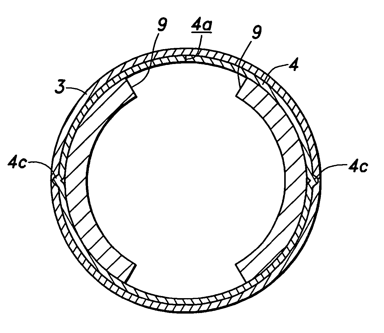
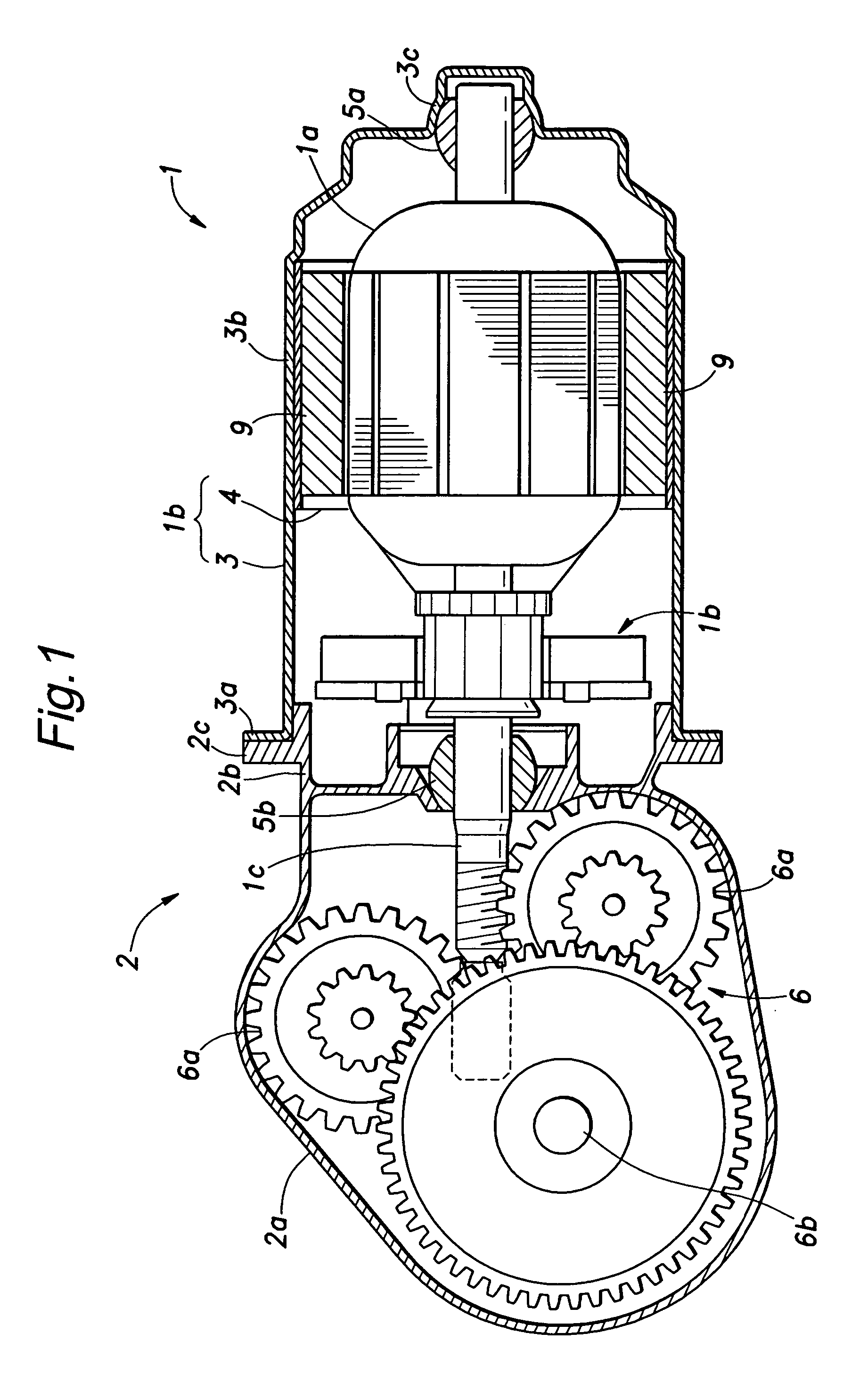
[0045]FIG. 1 is a sectional view of a motor unit embodying the present invention. The illustrated motor unit may be applied to an automotive wiper unit among other possibilities, and integrally incorporates an electric motor 1 and a reduction gear unit 2. The motor 1 comprises a rotor 1a and a casing 1b that surrounds the rotor 1a and serves as a yoke 1b. This yoke 1b is provided with a double-walled structure that includes a cylindrical cup-shaped outer yoke 3 and a tubular inner yoke 4 provided along the inner circumferential surface of the outer yoke 3. To the inner circumferential surface of the inner yoke 4 are attached a pair of arcuate permanent magnets 9 in a symmetrical arrangement.

[0046] The reduction gear unit 2 comprises a casing 2a that is provided with an open end configured to be connected to the open end of the outer yoke 3, and this casing 2a includes a cylindrical portion 2b that accommodates brushes 1b in sliding engagement with a part of the rotor 1a of the moto...


PUM

PropertyMeasurementUnit
Weightaaaaaaaaaa
Thicknessaaaaaaaaaa
Diameteraaaaaaaaaa

Abstract

Provided is a method for making a double-walled yoke that allows an inner yoke (4) and outer yoke (3) to be integrally joined to each other both easily and securely. Such a yoke provides an adequate cross sectional area for a magnetic path of the yoke while minimizing the weight of the yoke. A tubular member (14) destined to be form the inner yoke and a cup-shaped member (13) destined to form the outer yoke are both fitted on a punch (7) and a drawing process is executed by using an appropriate drawing die (8). The outer yoke may have a small wall thickness as long as it is capable of retaining its shape during use or supporting a bearing for the motor. The inner yoke is required to be relatively small in size as long it is capable of forming a satisfactory magnetic path for the motor. A satisfactory magnetic path can be obtained if the yoke is provided with an adequate wall thickness so as to provide an adequate cross sectional area for the magnetic path.

Description

TECHNICAL FIELD [0001] The present invention relates to a double-walled yoke including a cup-shaped outer yoke and a tubular inner yoke nested in and secured to the outer yoke in a coaxial relationship and a method of making such a double-walled yoke. BACKGROUND OF THE INVENTION [0002] A conventional motor casing typically comprises an end plate supporting a brush holder and a cup-shaped yoke connected to the end plate. The cup-shaped yoke is typically formed by a deep drawing process. FIG. 14 shows such an example. A radial outer flange 31a is formed at an open end of a cup-shaped yoke 31. The flange 31a is formed at the same time as forming the yoke 31 by a deep drawing process.[0003] The circumferential wall 31b of the yoke 31 that supports permanent magnets 32 is required to have a certain thickness so that a magnetic path having an adequate cross sectional area may be achieved. Therefore, the material for forming the yoke 31 is required to consist of a plate member having a cor...

Claims


Application Information

Patent Timeline
IPC IPC(8): H02K5/00H02K23/04
CPCH02K1/17H02K15/03Y10T29/49012Y10T29/49805Y10T29/49009
Inventor MIURA, TAKAHIROYOSHIZAWA, MASAYUKI
Owner MITSUBA CORP
Why Eureka
Try Eureka