Battery array

a battery array and array technology, applied in the field of batteries arrays, can solve the problems of easy over- or over-charge, reduced capacity that can be completely discharged, and degraded batteries can be fully charged, so as to achieve uniform cooling, efficient cooling, and reduced temperature differentials in the plurality of battery modules housed in the holder case

Inactive Publication Date: 2007-03-01
SANYO ELECTRIC CO LTD
View PDF1 Cites 40 Cited by
  • Summary
  • Abstract
  • Description
  • Claims
  • Application Information

AI Technical Summary

Benefits of technology

[0014] The battery array described above has the characteristic that temperature differentials in the plurality of battery modules housed in the holder case can be reduced, and battery modules can be cooled uniformly. This is because the battery array of the present invention houses three or more levels of battery modules in a holder case that forms an enclosed chamber bounded by a pair of opposing sidewalls, an inlet panel on the inlet side, and an outlet panel at the outlet side. Cooling air intakes are opened on both sides of the inlet panel, and cooling air passes between battery modules and opposing sidewalls. An exhaust opening to the outside is opened in the central region of the outlet panel, and cooling air passes along battery module surfaces to be exhausted at the central region of the outlet panel. Further, projections that protrude between adjacent battery modules are provided in opposing sidewalls, and the height of the interior surfaces of those projections increases from upstream to downstream.
[0015] Since cooling air from air intakes opened on both sides of the inlet panel flows between battery modules and opposing sidewalls, excessive cooling of a battery module at the cooling air intake side compared to other battery modules can be prevented in a battery array of this configuration. Since cooling air that flows along the surface of a battery module is exhausted to the outside from an exhaust opening through the central region of the outlet panel, a battery module at the outlet side can be efficiently cooled. Further, since the height of projections provided between adjacent battery modules increases from upstream to downstream, cooling gaps established between battery modules and projections become narrower towards the downstream side, and cooling gap area increases towards the downstream side. Consequently, the flow rate of cooling air, which has acquired battery module heat and risen in temperature, increases towards the downstream side, the contact area between cooling air and battery module increases towards the downstream side, and the amount of heat transfer at the downstream side can be increased. In this manner, temperature differentials in a plurality of battery modules housed in three or more levels in a holder case of the battery array of the present invention can be reduced and all battery modules can be cooled uniformly.

Problems solved by technology

Various problems arise if temperature differentials develop between the batteries being cooled.
If a battery with reduced charge capacity is connected in series and is charged and discharged with the same current as other batteries, it can easily be over-charged or over-discharged.
This is because the capacity to which the degraded battery can be fully charged and the capacity that can be completely discharged become smaller.
Battery characteristics degrade dramatically with over-charging and over-discharging.
In particular, if the battery's temperature becomes high, degradation is further increased.
In addition, each holder case had cooling gaps established between the holder case and the battery modules housed inside.
However, if battery modules are stacked inside a holder case in three levels or more to reduce the overall battery array footprint, this type of battery array becomes unable to uniformly cool each battery module.
However, all battery modules cannot be cooled to a uniform temperature with this configuration.

Method used


Image

  • Battery array
  • Battery array
  • Battery array

Examples


Embodiment Construction

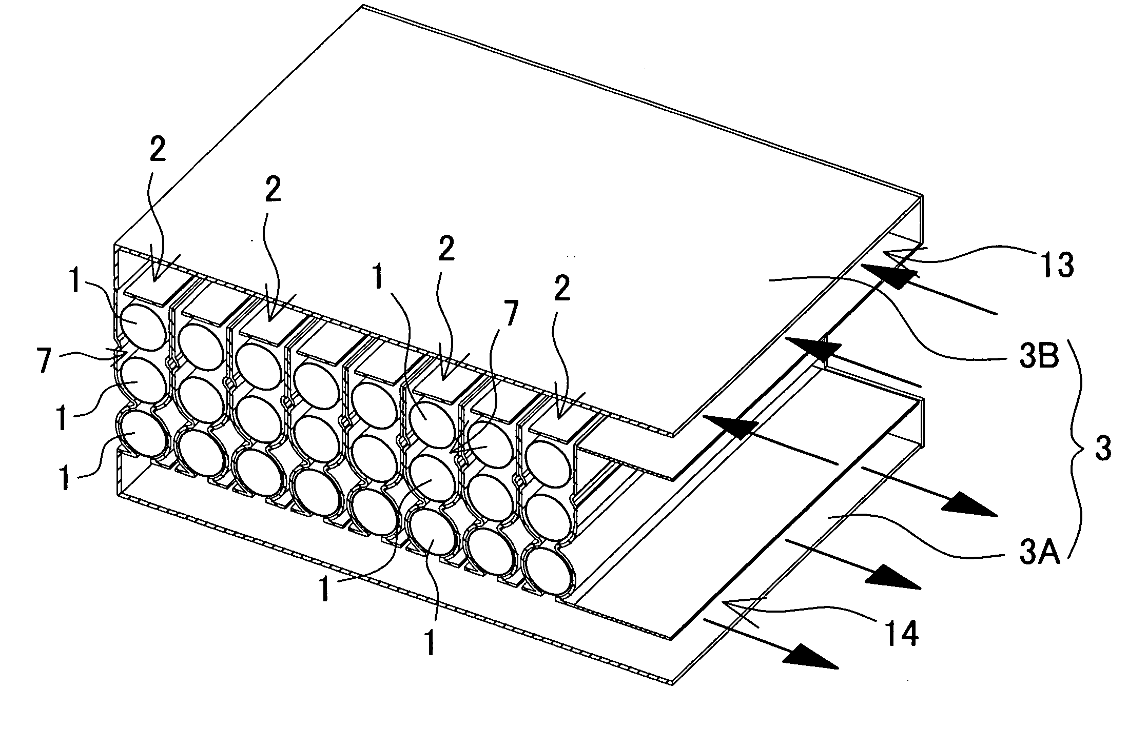
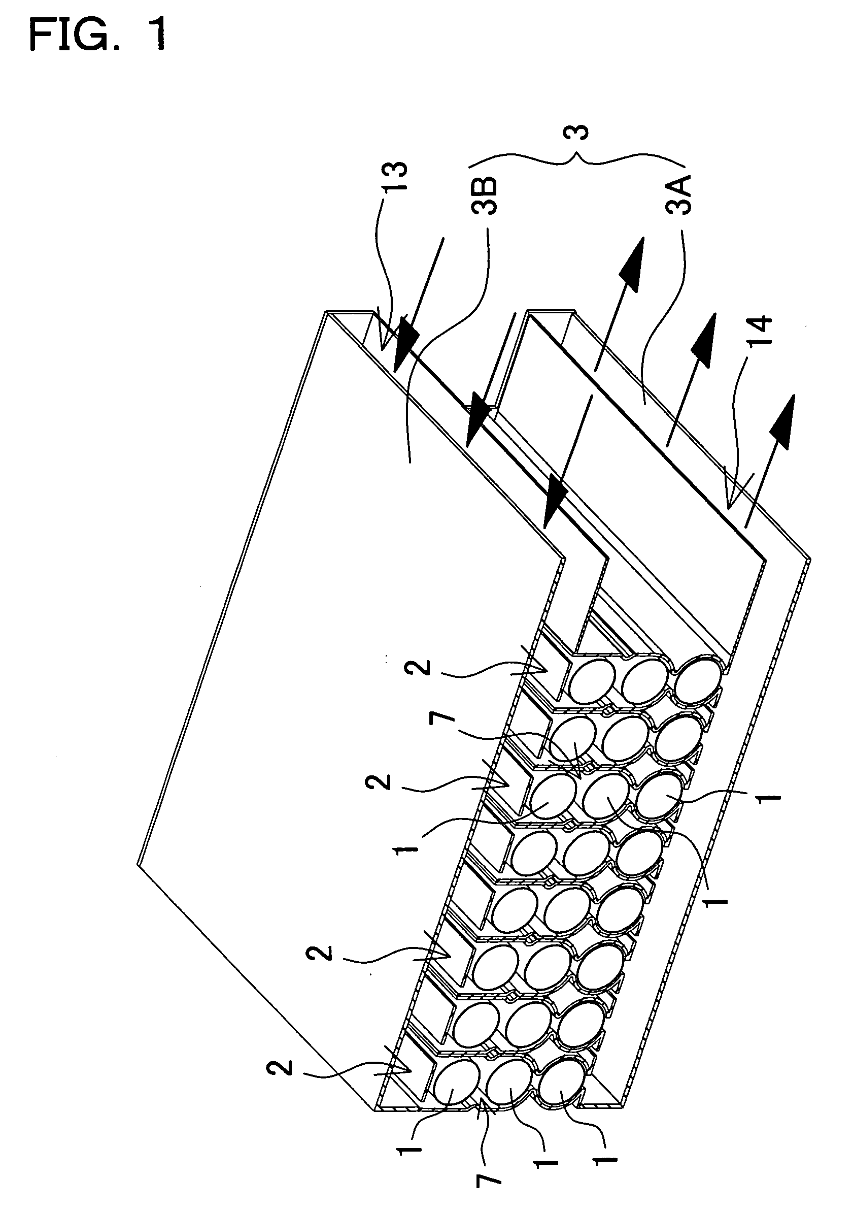
[0032] The battery array shown in FIG. 1 houses a plurality of holder cases 2 connected in a straight-line arrangement inside an outer case 3. Each holder case 2 houses a plurality of battery modules 1, and a battery module 1 is a series connection of a plurality of individual battery cells joined in a straight-line fashion. Each of the plurality of battery modules 1 housed in each holder case 2 are connected in series. However, holder case battery modules may also be connected in series and parallel.

[0033] The battery array of the figure is provided with an inlet air duct 13 between the outer case 3 and the holder cases 2 to supply cooling air to the holder cases 2. The battery array is also provided with an exhaust duct 14 to exhaust cooling air from inside the holder cases 2. In this battery array, cooling air flows from the inlet air duct 13, inside the holder cases 2, to the exhaust duct 14, and when the cooling air passes through the interior of the holder cases 2, it cools t...


PUM

PropertyMeasurementUnit
output voltagesaaaaaaaaaa
heightaaaaaaaaaa
electric poweraaaaaaaaaa

Abstract

The battery array cools battery modules 1 by flowing cooling air through a holder case 2 housing three or more levels of battery modules 1. A holder case 2 has a pair of opposing sidewalls 4 that are closed off by an inlet panel 5 on the inlet side and an outlet panel 6 on the outlet side to form an enclosed chamber 7 that houses battery modules 1. The inlet panel 5 has cooling air air intakes 8 opened on both sides. The outlet panel 6 has an exhaust opening 9 at its central region to exhaust cooling air. Opposing sidewalls 4 have projections 10 between adjacent battery modules 1, and the protrusion height of the inner surfaces of those projections 10 increases from upstream to downstream in the cooling air flow.

Description

BACKGROUND OF THE INVENTION [0001] 1. Field of the Invention [0002] This invention relates to a battery array that connects many individual battery cells in series or parallel, and in particular relates primarily to a battery array used as a power source apparatus to power an electric motor that drives an automobile. [0003] 2. Description of the Related Art [0004] An electric vehicle such as an electric automobile or hybrid car, which is powered by both an internal combustion engine and an electric motor, uses a battery array of many connected individual battery cells as a power source to supply electric power to the motor for driving. [0005] A battery array used in this type of application should establish high output voltage to supply power to a high output motor. Consequently, many individual battery cells are connected in series and housed in a holder case. For example, battery arrays installed in hybrid cars currently on the market connect several hundred individual battery cel...

Claims


Application Information

Patent Timeline
Patent Type & Authority Applications(United States)
IPC IPC(8): H02J7/00H01M2/10H01M10/60H01M10/613H01M10/617H01M10/625H01M10/652H01M10/6556H01M10/6563
CPCH01M2/105H01M10/5004H01M10/5008H01M10/5073H01M10/5038H01M10/5071H01M10/503H01M10/613H01M10/617H01M10/643H01M10/652H01M10/6565H01M10/6566H01M50/213Y02E60/10
Inventor SHIMIZU, HIDEO
Owner SANYO ELECTRIC CO LTD
Why Eureka
Try Eureka