MEMS acoustic filter and fabrication of the same

a technology of acoustic filter and acoustic filter, which is applied in the direction of microstructural device, mechanical vibration separation, instruments, etc., can solve the problems of narrow bandwidth of pzt transducer, high cost, and complicated process

Active Publication Date: 2007-03-01
KOLO MEDICAL (SUZHOU) CO LTD
View PDF2 Cites 57 Cited by
  • Summary
  • Abstract
  • Description
  • Claims
  • Application Information

AI Technical Summary

Benefits of technology

[0019] In one embodiment, MEMS resonator is a first-order resonator. In another embodiment, the MEMS resonator is a higher-order resonator. The higher-order resonator may have a plurality of first-order resonators. The plurality of first-order resonators may be stacked on one another. In one embodiment, MEMS resonator comprises a first resonator and a second resonator, wherein

Problems solved by technology

This process is fraught with difficulties and high expenses, not to mention the large input impedance mismatch problem presented by such elements to transmit/receiving electronics.
In general, both matching layers and backing layers are needed for PZT transducer because the significant mismatch of the acoustic impedance between the PZT material and the medium.
One of the

Method used


Image

  • MEMS acoustic filter and fabrication of the same
  • MEMS acoustic filter and fabrication of the same
  • MEMS acoustic filter and fabrication of the same

Examples


Embodiment Construction

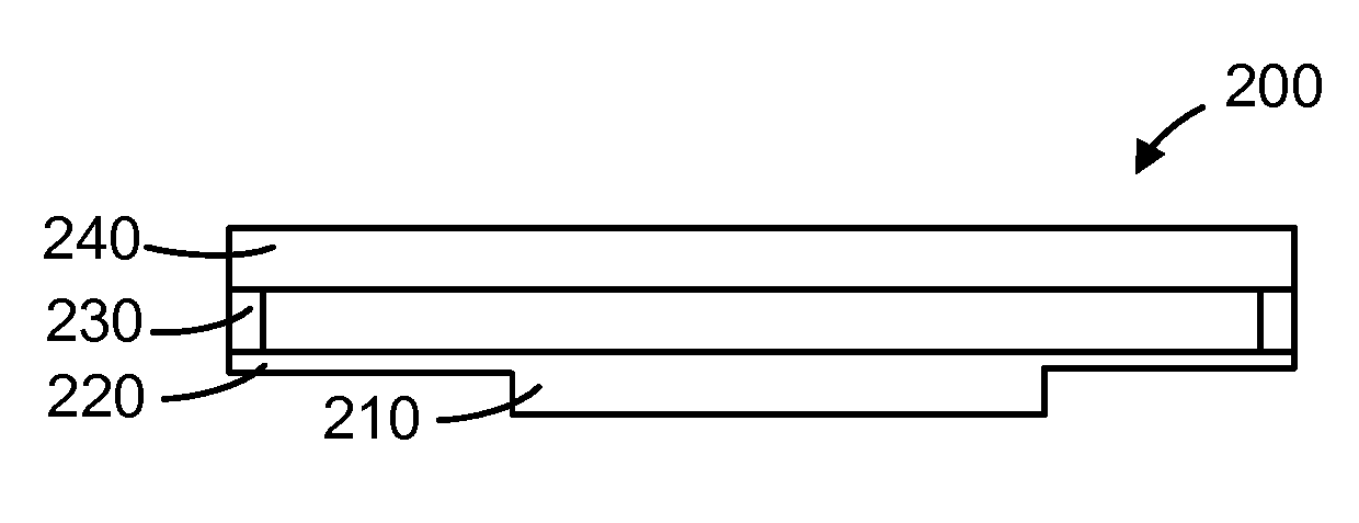
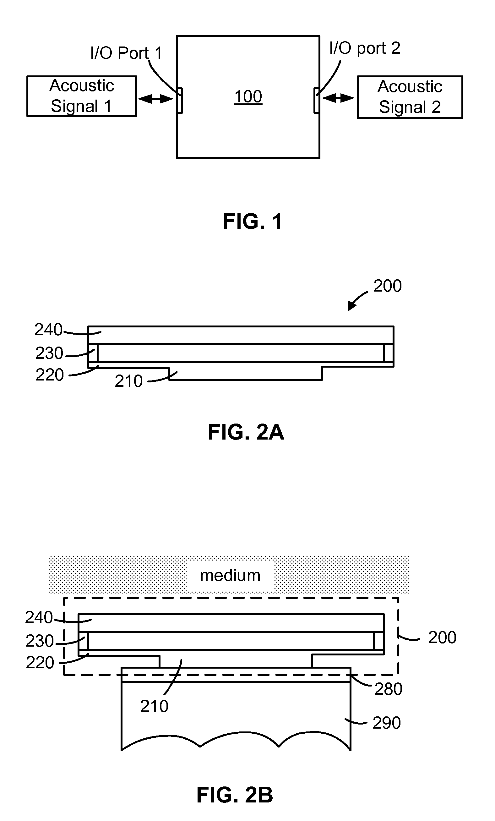
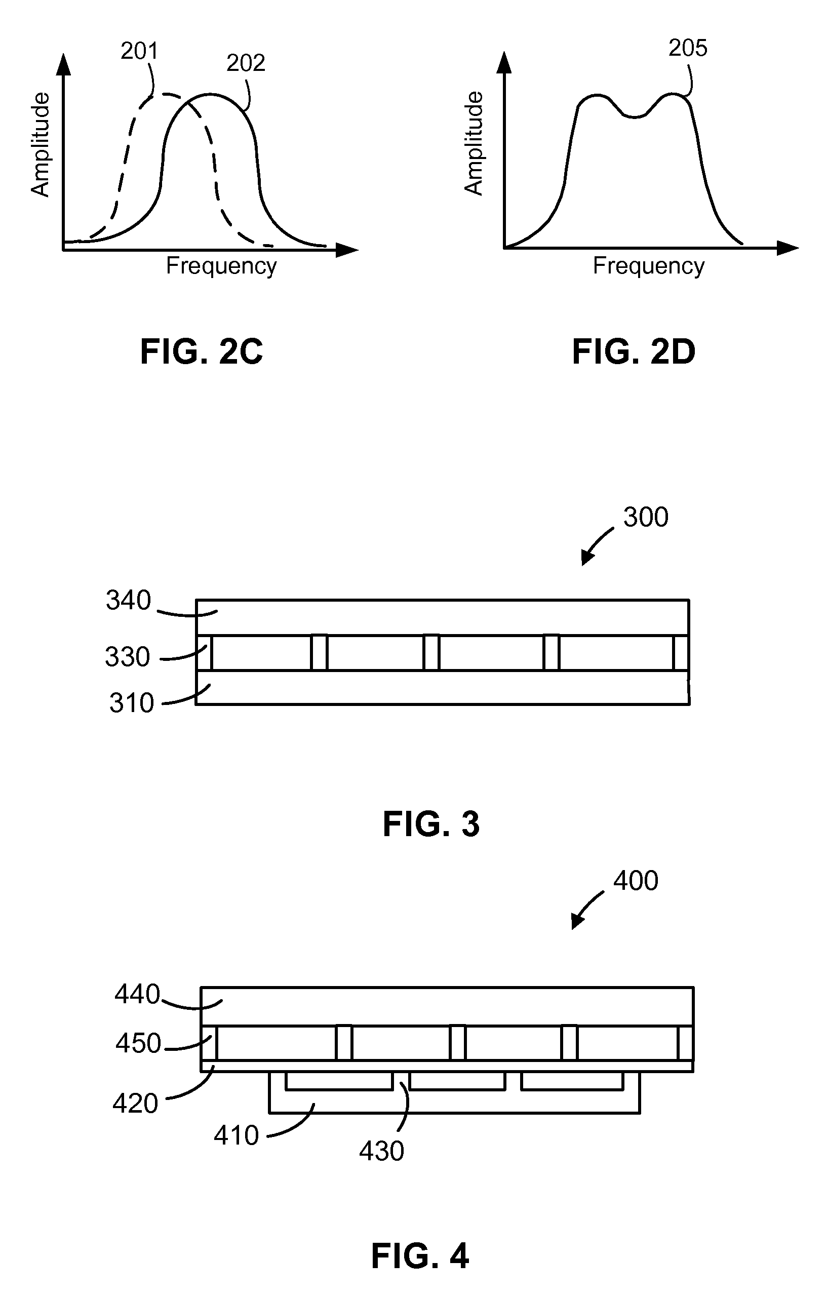
[0051] The MEMS acoustic filter for altering an ultrasound signal in accordance with the present invention will be described in detail along with the figures, in which like parts are denoted with like reference numerals or letters. The MEMS acoustic filter may be used with a variety of acoustic transducers including PZT and micromachined ultrasonic transducers (MUT). The MEMS acoustic filter may be fabricated using the novel fabrication methods described herein, but may also be fabricated using any suitable methods. Particularly, some embodiments of the MEMS acoustic filter of the present invention may be fabricated using similar methods for making micromachined ultrasonic transducers, such as the methods disclosed in the several patent applications reference to and incorporated herein.

[0052] The invention has been described below with reference to specific embodiments. In most cases, a PZT transducer or cMUT structure is used to illustrate the invention. It is appreciated, however...


PUM


Abstract

A MEMS acoustic filter has a MEMS resonator and at least two acoustic I/O ports to alter an input acoustic signal to an output acoustic signal. The first I/O port is adapted for interfacing with a medium, and the second I/O port for passing an acoustic signal to an acoustic transducer. Multiple MEMS resonators may be stacked to form a high order acoustic filter. An array of MEMS acoustic filters may be designed to function as an acoustic lens. The MEMS acoustic filter is particularly useful with an ultrasonic transducer, such as PZT and MUT. Fabrication methods to make the same are also disclosed.

Description

PRIORITY [0001] This application claims priority from U.S. Provisional Application Ser. No. 60 / 705,606, filed Aug. 3, 2005, which application is incorporated herein by reference in their entirety. [0002] This application further incorporates herein by reference in entirety the following: [0003] International Application (PCT) No. PCT / IB2006 / 051567, entitled METHODS FOR FABRICATING MICRO-ELECTRO-MECHANICAL DEVICES, filed on May 18, 2006; [0004] International Application (PCT) No. PCT / IB2006 / 051568, entitled MICRO-ELECTRO-MECHANICAL TRANSDUCERS, filed on May 18, 2006; [0005] International Application (PCT) No. PCT / IB2006 / 051569, entitled MICRO-ELECTRO-MECHANICAL TRANSDUCERS, filed on May 18, 2006; and [0006] International Application (PCT), PCT / IB2006 / 052658, entitled MICRO-ELECTRO-MECHANICAL TRANSDUCER HAVING A SURFACE PLATE, filed on Aug. 3, 2006.FIELD OF THE INVENTION [0007] The present invention relates to micro-electro-mechanical devices that have a movable mechanical part to fun...

Claims


Application Information

Patent Timeline
IPC IPC(8): H03H9/00
CPCB06B1/0292B81C1/00103G01N29/2406H03H3/0072H03H9/02259H01L2924/0002H03H9/2405H03H9/462H01L2924/00
Inventor HUANG, YONGLI
Owner KOLO MEDICAL (SUZHOU) CO LTD
Why Eureka
Try Eureka